• The move to the new server is done. There are some software and database maintenance updates in process. This has us passing the hat around to help out. We appreciate any donations. Seriously, even a dollar helps. The payment page may be found here - https://www.audiokarma.org/support.html

Luxman L-430 Recap / Overhaul

Trevor White

Classic not Plastic
Hi All,

I purchased a new Luxman L-430 Duo Beta integrated amp in December 1984. At the time it was $859 Australian Dollars. Anyway, the unit has provided sterling service for the last 34 years, although for some 20 years in there it was only occasionally and lightly used.

Recently though, following the restoration of my Pioneer RT-707 RTR, I have had a lot more time on my hands and have been using the amp a lot. I listen to a very broad range of music at moderate volumes. The Luxman drives my modern KEF speakers very well, although the KEF's are a lot more efficient than my old West German WIGO 4 ways that I retired for the KEF's. So although the amp is probably not being driven really hard I was concerned about the state of the Electrolytic's in the machine.
index.php


So I decided to take the plunge and recap the amp, despite the fact that it was working perfectly. I have documented the process as I went along and thought I would post a thread with the details and pictures to possibly help others that may want to tackle their Luxman.

This is a LONG post, broken up into 4 sections.

First job is to remove the top cover and base. Followed by the front fascia. The covers are simple to remove being retained by obvious screws. The front fascia is retained by three screws along the top and two on the bottom. The control knobs are removed by pulling them off. It can take a good firm pull! I found the balance control to be quite stubborn. Be aware that the power transistors and the transformer are mounted very close to the base of the frame. I found it prudent to raise the unit up above my work table by sitting it on a couple of old BASF plastic tape boxes. This ensured the circuit boards, transistors etc were well clear of the table top.
index.php


You can also see that there are two cables with clip terminating plugs. These are attached to a pair of small circuit boards attached to the rear of the fascia plate. They are the Speaker selection and Recording mode LED connections.

Looking directly down on the L430 with all the original caps in situ.
index.php


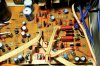
Here is the left hand side of the main circuit board. You can clearly see the two big 15,000uF/63V Nichicon Filter Caps. Most of the caps on the board are Rubycon's, although in this shot you can see two red/brown caps near the centre that are actually Elna's labelled as 'For Audio'.
index.php


This is the right hand side of the main circuit board. Again most of the smaller caps are Rubycon's except for four dark blue caps at the top and bottom far right of the board. These are also Elna caps.
index.php


This is the Tone Control board. It mounts the Bass and Treble controls and implements the Luxman's turnover frequency shift tone controls. Most of the caps on this board are Mylar film type, although there is one small Electrolytic.
index.php


Here is the Volume control board. This also contains the Phono input pre-amp and switch for the MC Phono impedance selection. There are a large number of signal cables attached to this board via little wire clamp connectors.
index.php


This is the foil side of the main circuit boards. If you look carefully you can see that I have already removed the big filter caps, exposing the selection of mounting holes that Luxman have provided.
index.php


And this is the underside of the transformer and voltage selection board.
index.php


Here is a close up of the main filter cap mountings. Luxman have provided mountings that support 4 and 5 pin Filter caps. There are also two sets of holes which support the 40mm x 80mm with 25mm pin spacing and also smaller caps with 22mm pin spacing. A bit of forward thinking by Luxman there.
index.php


And here is the component side of the board with the Filter caps removed. The glue used to secure these is a bugger to remove! You can clearly see here the selection of mounting holes.
index.php


Here is a close up of the right channel power transistors. My intention was always to leave these alone as there is no evidence that they need maintenance. Therefore these circuit boards I left in situ mounted securely to the heat sink. There are caps on these boards to be replaced, but it is possible to access them in place.
index.php


And of course the left channel transistors.
index.php


This is the foil side of the circuit board that supports all the switches.
index.php


In order to work on the L430 it is necessary to partially remove the front panel that the tone controls, volume and balance control are mounted to. This is relatively straightforward with two screws at each side. There are also small screws that secure the two upper circuit boards that must be removed. Additionally you need to remove the nuts that secure the tone controls, balance control and volume control.
index.php


In order to get enough room to free the tone control board and the volume control board you need to unclip ALL of the wires that attach to the volume control board. Be careful here! Make sure you carefully label the cables and draw yourself a diagram that indicates which connector is which. Once the volume control board is no longer constrained by the wiring you will be able to pull the front panel outwards and lift the circuit boards up so that the foil side can be accessed. You don't need a lot of room here. NOTE: There is a strip cable that runs from the MC Impedance switch to the upper volume control board. I could not work out how to disconnect it and so was just VERY careful when lifting this board up and working on it.
index.php


Here is a bit more detail of the tone control board moved out of the way.
index.php


And the volume control board. Note the labels on all the wiring.
index.php


Here is the volume control board ready for it's recap. The Electrolytics are obvious but there are also two little Mica 33pF caps in the Phono section. It is a little brown lozenge near the bottom of the image.
index.php


Continued in Post #2
 
Last edited:
Register to hide this ad
And here we go. Work begins! I actually elected to replace the Mica capacitors with modern Mica equivalents. Despite asking I could get no opinion from anyone here on AK as to whether they needed to be replaced. In any event there are only two 33pf and half a dozen 47pF Mica caps in the machine, so I chose to replace them. You can see the new Cornell Dubilier 33pF caps. The only voltage available in this size was 300V (that should be enough!) I had already decided not to replace any of the green Mylar film caps, they should all be just fine.
index.php


Now moving to the tone control board. The only electrolytic on here was a 4.7uF/50V which I chose to replace with a WIMA 4.7uF/63V Polypropylene Film cap.
index.php


On the bottom front circuit board that suports all the switches are a pair of .047uF/50V Ceramic Disc caps. I had also decided to replace these ceramics with WIMA Film caps as well.
index.php

index.php


Now, moving back to the volume control board I replaced the Electrolytic caps. I had chosen to use Elna SILMIC II caps for everything other than the big power supply rail caps. The Elna's are actually physically larger than other caps. Additionally I went up one voltage rating on every cap which did not help in the size stakes. But the Luxman was excellent in that it provided adequate space everyhere to use the Elna's without difficulty. You can see here though that the small value 4.7uF/50V Electrolytic's have been replaced by WIMA 4.7uF/63V Polypropylene Film caps.
index.php


Having replaced those caps on the tone control board and the volume control board it is possible to re-mount the front face of the amp and reconnect all the wires into their appropriate connectors. When inserting the wires into the connectors be sure to insert them carefully. You don't want to bend or damage the tinned ends of the wires. Once inserted you just close the plastic clip that clamps the wires and secures them. I just loosely fastened the nuts on the controls at this point, just enough to retain the circuit boards safely.
index.php


Here are all the wires successfully reconnected. There is a black ribbon style cable that connects in the bottom right corner. This one is a bugger to get fastened as the cable loops over the top of the connector.
index.php


The tone control board lightly remounted.
index.php


Now we move on to the two boards that support the power transistors. They are a bit awkward to get to the components from above, but not too difficult. There are a couple of Electrolytic's, a couple of Ceramic Discs and a couple of Mica caps as well. I chose to replace all of these.

Here you can just see the Electrolytic's under the heat sink.
index.php


Here you can see one of the 47pF Mica's and an Electrolytic. The Mica cap is the small brown lozenge to the upper left of the Electrolytic just about under the heat sink.
index.php


Here I have replaced the two .047uF/50V Ceramic Discs with a pair of WIMA .047uF/63V Film caps. Also, you can see that one of the Electrolytic's has been replaced by an Elna.
index.php


And there is the other Elna. You can see that it just clears the heat sink.
index.php


And here is one of the new 47pF/500V Cornell Dubilier Mica caps. Awkward to get in place right under the heat sink, but they have long lead wires which helped greatly. Also, these Mica caps are mounted between two legs of one of the transistors, so be careful when de-soldering and then remounting the new ones.
index.php


Now, the other two items on the transistor boards are the BIAS Current adjusting trimmers. The standard items are single turn 330ohm parts that in my machine had become stiff and VERY difficult to adjust the BIAS Current. So I elected to replace these with a pair of Bourns 3296Y Series 25 Turn trimmers. The Service Manual circuit diagram shows these parts to be 1Kohm, but the trimmers were actually only 330ohm linear. The closest Bourns makes to this is a 500ohm linear trimmer which will do nicely. The 3296Y trimmers do fit in the original holes, the pins are just long enough.
NOTE: When removing the old trimmers measure their values so that the new trimmers can be set initially close to the old settings.
index.php


OK, that completes these boards so we can move on to the main circuit board area.


Continued in Post #3
 
Last edited:
First cab off the rank is a pair .047uF/50V Ceramic Discs that were replaced with WIMA .047uF/63V Film caps. The one in this image is C834. C835 is a little further away.
index.php


Also. on the daughter board that holds all the AUX and Tape RCA inputs/outputs are another couple of .047uF/50V Ceramic Discs. To get to these you do need to dismount the Preamp In/Out daugther board, but that is very straightforward.
index.php

index.php


Now, here is the main circuit board with the larger Rubycon 'power supply' caps removed. There are four 470uF/100V and two 2200uF/35V parts. These were all glued to the main board and it was a bugger trying to clean up. If you look carefully at this image there are two Blue .047uF/100V Polypropylene Film caps right alongside the Speaker Relay. I also chose to replace these with WIMA Polypropylene Film caps.
index.php


In this shot two small value Elctrolytic's have been replaced with WIMA Film Caps. They are C832, a .47uF/50V replaced with a .47uF/63V WIMA and C813, a 1uF/50V replaced with a 1uF/63V WIMA.
index.php


This is a better view of the two original .047uF/100V Pp Film caps. I was of two minds whether to change these, but decided to do so anyway.
index.php


Here the two original Film caps have been replaced with WIMA .047uF/100V Polypropylene equivalents. Also the Electrolytic in front of them has been changed to an Elna.
index.php


Next are the two 470uF/10V Electrolytics.
index.php


Changed over to Elna SILMIC II 470uF/16V. You can clearly see here how much larger the Elna's are.
index.php


Now we come to the group of Electrolytic's that include the two original 'For Audio' Elnas. All of these replaced with Elna SILMIC II's.
index.php


Finally the last group of smaller Electrolytic's on the board. Notice the dark blue caps in the top left and right (one was already removed on the right hand side). These dark blue caps are also original Elna's, but despite asking I could not work out what was special about these guys that caused Luxman to use them rather than Rubycon's.
index.php


In any event I chose to use Elna SILMIC II's for all of them. Whilst doing these I also replaced the four 47pF/500V Mica caps on the main board.
index.php

index.php


Last but not least I moved on to the power supply caps. For these I chose (with advice from @mbz , @pwauk12 and @zaibatsu ) some Nichicon UHE series caps. These were used for the 470uF/100V and the 2200uF/50V replacements.
Also in this shot you can see two of the Cornell Dubilier 47pF/500V Mica caps. They are the two dark brown dumbbell shaped caps to the bottom right of the picture.
index.php

index.php

index.php


Continued in Post #4
 
Last edited:
Finally we have the main Filter caps. The originals were Nichicon 15,000uF/63V parts, but with no identification on them as to what series they may have been. Again with advice from @mbz and @pwauk12 I elected to use Nippon Chemi-Con parts. In this case a pair of KMH Series 18,000uf/80V parts. These matched the original physical size of the Nichicon's whilst offering slightly higher capacity. The slight increase from 15,000uF to 18,000uF will not cause any issues for the rectifier(s) or transformer.

**EDIT** Note that the 18,000uF Filter Caps did in fact cause a change in behavior of the amp! See this post for details (Post #13)

In this image one cap is mounted whilst the other I have upside down so you can see the pins. These are 5 pin caps, but the holes in the main board allow these to mounted without modification.
index.php


Finally both mounted.
index.php


And here we have the finished article.
index.php


Performing the BIAS Current adjustment. The Luxman Service Manual says 60mA plus or minus 10mA after 3 minutes from power on. The Bourns 25 turn trimmers made this very easy!
I also checked the DC Offset at this point after letting the amp warm right up. Left channel was a steady 12mV and Right channel was 1.9mV. I guess that will do.
index.php


But the acid test was to complete the assembly and put the old girl back into the system.
index.php


To my considerable relief the amp worked flawlessly. There was noticeably less 50Hz hum when the volume was cranked up with no input signal. On the whole the amp was just generally much quieter.

It also sounds as good as ever. I generally always run the amp with the tone controls switched out of the circuit (Tone Direct), and it has more bottom end punch whilst retaining it's smooth mid-range and clear open top end.

I had read that Elna SILMIC II's can take time to burn in? But if that is true then the amp sounds pretty damn good now, so I can hardly wait if it is going to get better!

More importantly this overhaul should see the Luxman performing well for many more years.

I hope you all may find this thread of some value. Please ask questions if you want more detail on specific items.

Cheers, and thanks for reading,
Trevor
 
Last edited:
g'day.. Nice!

Thanks for that mate.

I was of two minds whether I would post this thread. Some other threads I had started asking specific questions about the L430 received only a little interest. In some cases my queries went completely unanswered, so I was not sure how much interest there may have been in the Luxman integrated amp's. I decided to document the exercise anyway as someone in the future might come across the thread and find it useful.

Cheers
 
Luxman has a good repute from my reading and hens teeth in my locale. Many an owner who did post here don't usually post back w/ any issues. Ahhh the dreaded 50hz hum... noted on many 220-240 power. I'm not surprised it's 'quiet' now and looks nice in that home setup, too. Should offer many years service. (dual R to R's.. nice)
Q? is that heat sink the type with the gas tube? (or was it liquid..)
-----------
Many a reader here in the USA and world for that matter don't know that Australia has a very rich history of electronics and not just home audio and repair.
Bink.
 
The l430 is a very good amp. I've never had a chance to own one and they are going up in price here but was curious to see what it looks like from the inside. By the way that Lux looks great sitting in your shelf.
 
Great work and well documented. The L-430/L-410 are great amps!

If you haven't done it already...check all solder joints! Especially the solder joints from the TO-126 transistors.
Screenshot_46.jpg
If they're in bad condition and the contact isn't given, it can cause damages in the power amplifier section.

And change the relay... Someday (maybe tomorrow or in a few years; I don't know) it will cause contact problems.
 
Finally we have the main Filter caps. The originals were Nichicon 15,000uF/63V parts, but with no identification on them as to what series they may have been. Again with advice from @mbz and @pwauk12 I elected to use Nippon Chemi-Con parts. In this case a pair of KMH Series 18,000uf/80V parts. These matched the original physical size of the Nichicon's whilst offering slightly higher capacity. The slight increase from 15,000uF to 18,000uF will not cause any issues for the rectifier(s) or transformer.

In this image one cap is mounted whilst the other I have upside down so you can see the pins. These are 5 pin caps, but the holes in the main board allow these to mounted without modification.
index.php


Finally both mounted.
index.php


And here we have the finished article.
index.php


Performing the BIAS Current adjustment. The Luxman Service Manual says 60mA plus or minus 10mA after 3 minutes from power on. The Bourns 25 turn trimmers made this very easy!
I also checked the DC Offset at this point after letting the amp warm right up. Left channel was a steady 12mV and Right channel was 1.9mV. I guess that will do.
index.php


But the acid test was to complete the assembly and put the old girl back into the system.
index.php


To my considerable relief the amp worked flawlessly. There was noticeably less 50Hz hum when the volume was cranked up with no input signal. On the whole the amp was just generally much quieter.

It also sounds as good as ever. I generally always run the amp with the tone controls switched out of the circuit (Tone Direct), and it has more bottom end punch whilst retaining it's smooth mid-range and clear open top end.

I had read that Elna SILMIC II's can take time to burn in? But if that is true then the amp sounds pretty damn good now, so I can hardly wait if it is going to get better!

More importantly this overhaul should see the Luxman performing well for many more years.

I hope you all may find this thread of some value. Please ask questions if you want more detail on specific items.

Cheers, and thanks for reading,
Trevor
Right now the sound (while better) is Flat and Focused...At 25hr - 50hrs this will Open up and after 75hrs you will be rewarded of your work. Main Caps are Good...I also like 647-LKG1K153MKZ (Nichicon LKG).
 
Looks brand new, too! I'd bet OP is breaking it in on low volume while sleeping.. Opposite side of the world. :D
Great pics if I didn't say so.
bink.
 
Great work and well documented. The L-430/L-410 are great amps!

If you haven't done it already...check all solder joints! Especially the solder joints from the TO-126 transistors.
View attachment 1330478
If they're in bad condition and the contact isn't given, it can cause damages in the power amplifier section.

And change the relay... Someday (maybe tomorrow or in a few years; I don't know) it will cause contact problems.

Hi mate.

Yes, I carefully checked all the solder joints on the boards. They all looked to be in excellent condition. Also, I just happen to have a spare Luxman speaker relay, just in case :)

Cheers.
 
Right now the sound (while better) is Flat and Focused...At 25hr - 50hrs this will Open up and after 75hrs you will be rewarded of your work. Main Caps are Good...I also like 647-LKG1K153MKZ (Nichicon LKG).

Thanks for the tips about the Nichicon's. I did look at these, but they are too big! The originals are 60mm tall whilst the LKG's are 100mm!

Cheers.
 
Luxman has a good repute from my reading and hens teeth in my locale. Many an owner who did post here don't usually post back w/ any issues. Ahhh the dreaded 50hz hum... noted on many 220-240 power. I'm not surprised it's 'quiet' now and looks nice in that home setup, too. Should offer many years service. (dual R to R's.. nice)
Q? is that heat sink the type with the gas tube? (or was it liquid..)
-----------
Many a reader here in the USA and world for that matter don't know that Australia has a very rich history of electronics and not just home audio and repair.
Bink.

Hi Bink,

I'm not sure about the heat sink. I have read anecdotal evidence that it may be fluid filled, but I don't know for sure. Seems to work though, the unit rarely gets very hot, just comfortably warm after a good workout.

Cheers.
 
So did ya sleep on it? :D I would mate in damned hammock if I had one... I'm yank but knew quite a few aussies in canader.. nice mates! Not stuffy ya know? Adelaide and all that west coast are a dream to me to visit.. shoulda done it when I was wild and had the bucks. I used to frequent some of your electronics forums and came across some interesting like AK albeit ya need a dictionary sometimes..
:rflmao::beerchug:
Pics and whole post is a real piece of work mate! Damned as noted boards look like you just took it out of the plastic new.

btw if the Sink has a tube? is dead give-away for something inside but maybe open on each end? Just looking at the construction to make the damn sink assembly must be efficient.. It ain't some kinda food warmer. :D
Cheers.. pm is always open!
Can ya post some aussie forum links?
 
Great work and well documented. The L-430/L-410 are great amps!

If you haven't done it already...check all solder joints! Especially the solder joints from the TO-126 transistors.
View attachment 1330478
If they're in bad condition and the contact isn't given, it can cause damages in the power amplifier section.

And change the relay... Someday (maybe tomorrow or in a few years; I don't know) it will cause contact problems.

Actually @Luxman, did you mean to just visually inspect those TO-126 solder joints, or maybe actually re-flow the solder to be absolutely sure?

Thanks.
 
If they look like your pics soldering they're good. board looks well flowed. and no issues with testing.
 
So did ya sleep on it? :D I would mate in damned hammock if I had one... I'm yank but knew quite a few aussies in canader.. nice mates! Not stuffy ya know? Adelaide and all that west coast are a dream to me to visit.. shoulda done it when I was wild and had the bucks. I used to frequent some of your electronics forums and came across some interesting like AK albeit ya need a dictionary sometimes..
:rflmao::beerchug:
Pics and whole post is a real piece of work mate! Damned as noted boards look like you just took it out of the plastic new.

btw if the Sink has a tube? is dead give-away for something inside but maybe open on each end? Just looking at the construction to make the damn sink assembly must be efficient.. It ain't some kinda food warmer. :D
Cheers.. pm is always open!
Can ya post some aussie forum links?

Thanks Bink,

I was also surprised at how good the unit was inside after 34 years. As you can see from the pics it is fairly well shielded from above so I guess not a lot of dust got in there. I did blow/brush the dust off and wash the boards with some IPA before starting work. It has certainly tuned out very nicely. The heat sink definitely has a central bar that is not solid, and is enclosed at each end, it is not a 'tube' as such like some of the earlier types, but it looks like it could well have something inside of it.

Adelaide is actually on the South Coast of Oz, closer to Melbourne and a long way from Perth that is on the West Coast ;)

Actually I don't frequent any Australian audio forums, I have always used AK and TapeHeads.:dunno:

Cheers mate, and thanks :thumbsup:
Trevor
 
Back
Top Bottom