• The move to the new server is done. There are some software and database maintenance updates in process. This has us passing the hat around to help out. We appreciate any donations. Seriously, even a dollar helps. The payment page may be found here - https://www.audiokarma.org/support.html

MAC 4100

I would first separate the preamp section from the power amp (pull the jumpers) to see if the noise is coming from the power amp section or from the preamp section.

If it still pops therefore from the amp section, you will need to do a stress test.

A few months ago I showed a picture of MA6200 failing a stress test of the main filter caps, while the main filter caps have been surprisingly resilient they are due to start failing at sometime.

If it does not pop with the two sections separated you would have to suspect the preamp section. I just recap all sections now, driver boards, EQ, PS, loudness, etal.......except the tuner unless the tuner needs a alignment......
 
I would first separate the preamp section from the power amp (pull the jumpers) to see if the noise is coming from the power amp section or from the preamp section.

If it still pops therefore from the amp section, you will need to do a stress test.

A few months ago I showed a picture of MA6200 failing a stress test of the main filter caps, while the main filter caps have been surprisingly resilient they are due to start failing at sometime.

If it does not pop with the two sections separated you would have to suspect the preamp section. I just recap all sections now, driver boards, EQ, PS, loudness, etal.......except the tuner unless the tuner needs a alignment......

With the jumpers pulled out, it still pops when turned on, but not as loud. With the jumpers out, I do not hear any pop, when turned off.

I don't think I have the skill-set to perform a stress test. Is your confidence high that replacing the capacitors will solve the problem? Which board do think is most likely to be introducing the problem?

Thanks again for your insight.
 
Scott - read my thread on the relay issue I had in my 4100. I don't remember if mine popped like yours does, but I had to install a new relay in mine. Somewhere along the way during the production run McIntosh switched from 24V to 48V relays (or the other way around) and issued a service bulletin with information on the conversion. My unit had the wrong voltage relay installed. It still worked, but the relay was not happy about it. I may be hazy on the details, but I documented all of this in my 4100 thread.

I would measure across the coil of your relay to make sure that what you think is there is actually there in terms of voltage.

-Matt
 
So you have confirmed that the preamp section, or a input plugged into the preamp and selected, is causing a noise and the power amp section is also to blame.

Typically the relay would keep the noises out of the speakers by engaging after the sections powered up and settled down and opening before you could hear the sections decay.

While it might be a tech satisfying endeavor to find out which component is at fault at some point it just makes sense to do a complete recap of all the boards. Time is money.

While I have these units apart I also will reflow the molex pin connectors as they are known to crack because of their thermal mass.

The main filter caps stress test needs a big enough load to allow the unit to try to make max power at 20 Hz. I do not have to take my shoes off to count how many of Mac's main filter caps I have found faulty over the decades but they are getting very much past their expected life span.
 
The voltage at the coil is 48 vdc. The relay was recently replaced with a new 24 vdc relay (Omeron LY2). I temporarily swapped the 24 vdc relay with the original 48 vdc relay (Eagle 14Q2CD048 ) and it didn't resolve the popping problem.

I removed the preamp/amp jumpers and the popping still occurs when the 4100 is turned on. I tested the 4100 preamp by connecting the 4100 preamp out to the line line in on another receiver and set of speakers. I tested the 4100 amplifier section by connecting the line out of the other amplifier to the amp in on the 4100. The popping occurred on all three tests (no jumpers only, preamp isolated, amp isolated).

Any additional suggestions that might help isolate the source of the popping would be greatly appreciated. Thanks!
 
So you have a transient from both the preamp section and the power amp section.

Is one upon turn on, one when turned off?

Have you recapped the whole unit or just the power supply?

The unit is 40 years old so the electrolytic caps are well past their expected lifespan.

Obviously there is a imbalance within the circuitry that is allowing the unit to cause the transient......to find that imbalance will involve bench time with a scope and other test gear.

Turn on, turn off transients are not uncommon......going back to the begining of radio and audio there has always been a sequence of how you power up and power down equipment to minimize them. It would seem that your unit is acting up outside the parameters that Mac designed to keep them outside of your speakers.

Time to get it back to your tech.
 
So you have a transient from both the preamp section and the power amp section.

Is one upon turn on, one when turned off?

Have you recapped the whole unit or just the power supply?

The unit is 40 years old so the electrolytic caps are well past their expected lifespan.

Obviously there is a imbalance within the circuitry that is allowing the unit to cause the transient......to find that imbalance will involve bench time with a scope and other test gear.

Turn on, turn off transients are not uncommon......going back to the beginning of radio and audio there has always been a sequence of how you power up and power down equipment to minimize them. It would seem that your unit is acting up outside the parameters that Mac designed to keep them outside of your speakers.

Time to get it back to your tech.

The popping is on both channels when powered on but is usually only on the right channel when powered off. So far, I've only recapped the power supply board.

Do you think it's likely that recapping the rest of the receiver will resolve the problem? If you had to take a guess, which board (or boards) do you think would be most likely to be introducing the imbalance? Thanks.
 
I have no idea.....a proper sequential bench test would be needed.

There is supposed to be a delay for the relay to close once the amp has settled down. Reality is that amp sections as well as preamps can make a racket until their supplies charge up and voltages balance. The turn on delay is supposed to hold off closing the relay until these things settle down.

The schematic does not state a time for the delay but it usually is a few Mississippis......the turn off and relay opening should be instantaneous.
 
I have no idea.....a proper sequential bench test would be needed.

There is supposed to be a delay for the relay to close once the amp has settled down. Reality is that amp sections as well as preamps can make a racket until their supplies charge up and voltages balance. The turn on delay is supposed to hold off closing the relay until these things settle down.

The schematic does not state a time for the delay but it usually is a few Mississippis......the turn off and relay opening should be instantaneous.

The relay energizes immediately upon power on. There is 3 second delay (approx) before the relay returns to a non-energized condition after the power is turned off. Is there a way to adjust the power on delay? Do you know which board controls the power on delay?
 
It is working bass ackwards......the offset sensing transistors are on the PS board.

Are the sensing transistors Q604 and Q605 (see screenshot)? It doesn't sound like this is something that will be resolved by recapping the other boards. Now that we know the delays are working backward do you have any suggestions?
Power Supply Protection Relay Transistors.png
 
It is working bass ackwards......the offset sensing transistors are on the PS board.
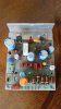
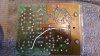
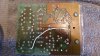
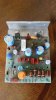
I took a closer look and it appears the power on/off delay has been modified (see attached screenshots). I'm going to put it back the way the schematic indicates and see if it fixes the problem. It looks to me like the "Mystery Jumper" is also part of the delay bypass and should be removed after I undo the other bypass modifications. Do you agree? Do you have any idea why someone would make this kind of modification?
Power Delay Modifications.jpg Mystery Jumper.jpg
 

Attachments

  • Mystery Jumper.jpg
    Mystery Jumper.jpg
    92 KB · Views: 47
  • Mystery Jumper.jpg
    Mystery Jumper.jpg
    92 KB · Views: 45
There is a trace that snakes around from the collector of Q601 to the resistor (R601) that connects to Molex pin 14 which is the 40 volt supply to the thermal sensors and relay.

If you follow the trace from the trace side of the board in the schematic you can see that this supplies a voltage to the control transistor for the regulated power supply as well as the turn on delay transistor.

Who knows what demon the previous owner was chasing down. If there is continuity via the trace the wire jumper is superfluous.
 
I'm going to replace D608 and R601 (both are strapped and missing) and see how it goes... Any other suggestions would be appreciated. Thanks for your assistance!
 

Attachments

  • Missing D608-R601.jpg
    Missing D608-R601.jpg
    43.8 KB · Views: 22
I have a RT909 spread all over my bench and more importantly a Tball game beckoning. See note #10 for insight.
Image (12).jpg
 
It looks like note 10 is only relevant for serial # BY1900 and below and My 4100 is serial number BY2457. Thanks for your assistance and enjoy the day!
 
Little league in the mitten in May......better wear a snowmobile suit.

Even though note 10 refers to a earlier serial number so many of the parts are referenced by you and in it, it would seem it might give some insight into what was being attempted previously.

It would seem to make sense to rebuild it to spec and see what happens but do ave to say that a quick glance would cause me to suspect the 15 volt zeener which appears to be a central part of the turn on delay.

Also I have come to have no confidence in the orange plastic electrolytic caps.
 
I'm ordering the parts tomorrow, including a new zener which is completely missing. Thanks for your insight... Play ball!
I was unable to resolve the problem so I brought my receiver to the Doctor (Cornell). He replaced the missing components and now I am enjoying my receiver without the annoying popping sound. I love the way this receiver sounds through my JBL 4311s... Thanks for all your help and comments!
 
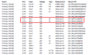
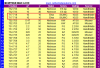
Could you please take a quick look at the attached screenshot and confirm that I should use the Nichicon PW type caps for the purple caps and a Nichicon FG type cap for the orange cap? View attachment 1482970
Hi Matt. I'm in the process of recapping my 4100. I am currently recapping the pre-amp audio switching board 045220. I ordered the caps from Mouser using a parts list I found on this board and may have originated with you (see attached screenshot). I found another parts list (also on this board) that lists different 10uf/25v caps. The cap on one list (in positions 717 and 718) has no polarity but the Elna SILMIC 10/25 on the other list (also in positions 717 and 718) has polarity. The original cap I'm replacing also has polarity so I'm a little nervous about the conflicting polarity issue. Could you reassure me that I can use the UES1C100MDM caps instead of the Elna SILMIC 10uf 25v caps? Thanks!
 

Attachments

  • 10uf-16v from Matt.png
    10uf-16v from Matt.png
    26.4 KB · Views: 18
  • 10uf-25v from cathedralspeakers.png
    10uf-25v from cathedralspeakers.png
    31.7 KB · Views: 16
Back
Top Bottom