• The move to the new server is done. There are some software and database maintenance updates in process. This has us passing the hat around to help out. We appreciate any donations. Seriously, even a dollar helps. The payment page may be found here - https://www.audiokarma.org/support.html

Mag 175-67 rebuild. Questions, Questions........

Strgazr1967

Active Member
Good evening,

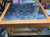
I picked up this 175 in decent shape. Tubes are not the best but that will be corrected. I’ve been pouring over as many threads on this amp as I could find and therein lies a problem. There is so much info on AK I am a bit overwhelmed and confused about some things. Hoping I can use this one thread to gather info, maybe brainstorm at times and get me to a point of a nice sounding amp done right. I can read a schematic to a point and have a basic understanding of certain electronic theories as well as a fairly skilled with a soldering iron. (Just picked up a Hekko 880 and LOVE IT). There is such a wealth and depth of incredibly good tube experts here I am falling back on you guys lol.

I am trying to put together a list of materials but am getting confused. Coupling caps are first up. Is it worth the money to go high end on these or is that money better spent elsewhere? What would you guys recommend? I’m thinking Orange drops? The large silver Magnavox caps also have to go if I’m correct. What should they be replaced with? I have noticed that a few of the caps on this amp have differing values than that shown on the sams schematics. Yet they look original. Trying to find .0033 mf caps has been daunting. Can they be upped in value without concerns? I have seen differing opinions on wether to remove the balance pot or not. I would like to but don’t know how to do this effectively. I plan on replacing all the resistors in the unit. I’ve noticed that there is a difference in the resistor/cap combos on the output side. Should I replace the caps and use matching values? If so should I stay the same or go up in value? As I am removing the molex plugs and my house voltage runs around 123vac would it be wise to use the existing windings from the molex that ran to the preamp/tuner as a bucking setup? I have already added an IEC socket, fuse holder, power switch and vintage indicator lamp. I will have the RCA and speaker jacks as well as the CL-80 thermistor in tomorrow hopefully. I’ve started on a wood frame of solid cherry taken from stock found in a barn near our cabin in NH last summer. Just needs a few more coats of oil to finish and add the feet.

I apologize for the long winded post. If anyone has a list handy of what they replaced on their 175’s and would like to post it feel free. It would be greatly appreciated.

If anyone has any ideas or mods on this amp also feel free. I am going back and forth about swapping OPT’s to run 8ohm outputs but wonder if it’s worth it with my current speaker lineup. Primary speakers will be a pair of KG4’s with the Crites Xovers as well as his diaphragms for the tweeters. I could also swap in a pair of Advent Heritages, Advent 4002’s and Elac Debut B6 2.0.

Again, thanks so much in advance for any/all help you guys can offer.

199BC20B-8958-4C82-99CB-B270FB959BE0.jpeg
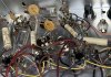
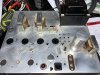
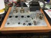
6BD7C607-1362-4087-BA44-E1BAFF56D288.jpegFD35F8A3-CB91-45B5-89D9-AA56C0959F36.jpeg1757877C-F8EB-4AA6-BC69-BFCFE7F7597D.jpeg
 

Attachments

  • B4D30950-CD04-4226-8787-9E7F62427FB2.jpeg
    B4D30950-CD04-4226-8787-9E7F62427FB2.jpeg
    116.6 KB · Views: 12
Register to hide this ad
Just curious, how do you know the tubes are not the best? Have you tested them? Usually, its the tubes that are the last to be dealt with unless they are very weak or internally shorted.
 
Just curious, how do you know the tubes are not the best? Have you tested them? Usually, its the tubes that are the last to be dealt with unless they are very weak or internally shorted.

The tubes are from 3 different manufacturers, one is showing signs of a crack with ghosting/powdering on the glass and the previous owner told me that he threw in a set of tubes on their way out just to verify it worked.
 
I am trying to put together a list of materials but am getting confused. Coupling caps are first up. Is it worth the money to go high end on these or is that money better spent elsewhere?
Decent but inexpensive coupling caps will work great for this amp. I'd use Illinois Capacitor brand coupling caps. You can get them at Antique Electronic Supply, Angela Instruments, and several other places.

Trying to find .0033 mf caps has been daunting.
0.0033 Micro Farad (uF) is the same as 3.3 Nano Farad (nF) which is the same as 3300 Pico Farad (pF). You can find 3300 pF caps at Mouser. Example this part number: ECQ-E6332JF3 is 33 cents/ea.

Can they be upped in value without concerns?
A Magnavox expert might know, but without seeing where that cap is on the schematic I wouldn't feel comfortable commenting. Sometimes it's okay, other times definitely not okay. It depends on how the cap is being used in the circuit.

I have seen differing opinions on wether to remove the balance pot or not.
I'd remove it and add a floating paraphase instead. (see below).

I’ve noticed that there is a difference in the resistor/cap combos on the output side. Should I replace the caps and use matching values?
If you are talking about the feedback circut from the secondary of the output transformer back to the cathode of the 12AX7 stage, then yes, I would make them both the same and remove the balance pot. Make both channels the same following the schematic of the channel without the balance pot in it.

As I am removing the molex plugs and my house voltage runs around 123vac would it be wise to use the existing windings from the molex that ran to the preamp/tuner as a bucking setup?
Yes. Should be the two brown leads at 6.3V (according to the SAMS schematic) that could be used to buck the primary if that's what you wanted to do.

If anyone has any ideas or mods on this amp also feel free.
A mod you should consider is converting the frontend paraphse inverter (the two 12AX7 triodes) into the floating paraphase configuration. You will need to research floating paraphase. There have been several members here do that conversion on Magnavox amps. Seems like it would be straight forward to find those threads with the search feature on the forum. Unfortunately I can't remember who did that conversion and on which Magnavox amp...but I do remember someone did it on some Magnavox amp here on this tube forum.

I will do some digging for a few minutes to see if I can remember/find the thread where floating paraphase was discussed.

===

I find the best way proceed generally in rework like this is to start with a readable schematic and mark it up with the changes you want. Get everything marked up/changed before you start doing any work. If you've already started the rework, mark up what you've done and post your changes for comments/confirmation. Taking time up front to get the design right and it will pay off later when you are making soldering changes, so you have a well conceived plan to systematically follow.
 
The balance pot on the 175-67 is a hum balance control and not a speaker balance so it needs to stay.

EDIT: Hmm, I see two pots on your chassis but my 175-67 only has one pot and it is a hum balance.
 
My comments were based on the 175-AA SAMS schematic, which has a 500K "input balance" pot on channel 2's input. I also see two pots in the pics above, one is near channel 2's input and looks like the pot in question.
 
I just finished rebuilding AMP-185 chassis. The difference is that 185 came out phono only consoles and phono preamp tube was on the amp chassis. Your 175 has that tube position covered with the plug. I added volume pot and it was suggested to me to convert that phono preamp tube into cathode follower buffer. You can add a socket in that position and do same. Here is my thread:
https://audiokarma.org/forums/index.php?threads/magnavox-amp-185-question.880953/

I faced fair amount of challenge getting the amp stable. Make sure to check for oscillation into variety of different loads.
Mine was only misbehaving into capacitive only load.
Do you have an oscilloscope?
 
The pot with black plastic rod is hum balance. The one with aluminum rod is channel balance, the one that needs to be eliminated.
 
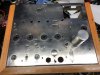
Sorry for the delay in getting back to this thread. I suffer from an annular tear issue with my L5/S1 discs and had surgery on Thursday last week to hopefully help with this. Hydrogel injection and bi-lateral cortico/steroid injections. Feeling pretty good all things considered. I have been able to sit at my bench and get some cosmetic work done on the unit including the wooden frame, removing the OPT's, PT and choke. Filled all the holes that are/wont be needed and gave it a clean up. I started mounting the RCA jacks, speaker jacks as well as the fuse and IEC socket. Not sure if the speaker jacks are staying. Cheesier then they looked in the ad. I have been pouring over thread upon thread trying to gather any info I can.

I am building this for myself and although it may not be worth investing a ton of money in I would like to make it as good as I can within my limits. What would be a real nice cap to replace the coupling caps with? I have looked at orange drops as well as some from Vishay. As far as resistors go can I get away with replacing the originals with carbon or are ceramics the way to go for the slight price difference? most are 1/2 watt based on the schematic except for a 1 watt and 10w if I remember off the top of my head. Would there be any advantage to moving the choke underneath or is it purely cosmetic? I'm torn between spending the money on a new can cap or trying to wire in new caps under the chassis and leave the can just for looks. Any thoughts on this?

I have been reading over this thread from Wharfcreek about swapping OPT's. I have a pair of KG-4's with Crites Xovers and Ti tweeters as well as a pair of Pioneer CSA-700's that rate out of 95db/1w. If there is a benefit to swapping to 8ohm OPT's I would consider the cost.

https://audiokarma.org/forums/index.php?threads/magnavox-175-replacing-ots-with.697353/page-2

I could really use some help with removing the balance pot, picking cap values that would improve the overall sound of the amp as well as adding in possibly the "Paraphrase Mod". So many of the threads I have found have images that are either no longer available or have been blurred out by the thieves at photobucket.

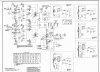
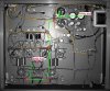
I have attached some chassis pics as well as the Sams for the unit.

If it's a lot to ask I understand. I have a basic knowledge of electronics, some schematic experience, a variac and a nice Techtronixs 2465B at my disposal.

Thanks!IMG_1916.JPG IMG_1917.JPG IMG_1919.JPG
 

Attachments

Last edited:
You could blow up the schematic by cropping certain sections of the schematic and posting them separately. For example the amplifier portion and the power supply portion. As I mentioned above, if you can post a legible schematic of the section you have questions about, it will help to get a good plan before you start soldering. That's a MUST in my book, otherwise you are just "hacking" on it and who knows what the outcome will be.

For coupling capacitors, I don't think it matters a lot on brand, so orange drops will work. I like Illinois Capacitor brand. You can get them at Antique Electronic Supply (aka tubes and more): https://www.tubesandmore.com/products/capacitor-630v-polypropylene-axial-leads

For resistors, I recommend carbon film or metal film types. If metal film, the 2 watt types are what I use, except where the dissipation in circuit will exceed the safety margin, then I go with metal oxide or wire wound. Example if in circuit the dissipation is less than 0.5 watts, then a 2 watt resistor gives some headroom without compromising the stability of the resistor.

You should locate the choke near the other power supply components, either on top or underside mounted is fine.

Personally I'd keep the 4 ohm output transformers for now. That can be a mod you add later. I think it's more important to get the rest of the amp working before you mess with the output transformers.

The paraphase mod is a whole separate discussion that won't fit into this post, but one worth having. What I will say here is the big problem with the standard paraphase inverter is it doesn't offer consistent performance as tubes age or if you swap out the tubes. The floating paraphase addresses a lot of that by adding local feedback around the "inverting" triode.

So in summary, the questions I'd start to address in the amplifier section for your build plan are:
1. How to remove the balance pot on that second channel.
2. What capacitor sizes to use. (that answer will typically be "keep them the same as in the original design", for reasons that will be explained as you delve into this question).
3. How to convert the inverter to the "floating paraphase?" You could even put this question in the "future" section below as this would ease your work load to getting a functioning amp that you could enjoy now while you learn more about the floating paraphase.

The questions in the power supply to address are:
1. Where to add the choke
2. How do I buck the primary?
3. How/where do I add a current inrush limiter (thermistor)

Future questions you might want to address after you get a working amp:
1. Should I swap out the output transformers for 8 ohm units?
2. Should I consider converting to solid state rectification?
3. Converting to floating paraphase.
 
K,

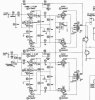
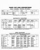
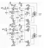
Thanks SO much for your input so far. I appreciate you taking the time to work with a "Tube Noob" like myself. I have attached (Hopefully) cropped sections of the Sams for the amp. I am currently going through both the Mouser site as well as Digikey and as you mentioned, Antique audio supply putting together a parts list. I am basing this off of the lists I have attached. I will hold off on a final order in case you see something that could be changed to improve the amp. Hopefully these are a good size to work with.

In regards to your "Questions to address before I start" I totally agree with them. And look forward to your help as well as anyone else who wants to chime in. It is also my hope that someone else with my experience level may learn from this thread also.

I will be placing the choke back in it's original location. I kind of like the look it gives. This also leaves more room underneath to work with.
I'm pretty confident I have the wiring down for bucking the primary using the spare 6.3v lines.
If I am correct the thermistor will go in line (series) with the hot side of the 120 supply.

If I am using a 3 wire power cord is there still a need for an X/Y cap to be installed?

Again, Thanks so much!
 

Attachments

  • Driver section.jpg
    Driver section.jpg
    63.8 KB · Views: 30
  • PS section.jpg
    PS section.jpg
    82 KB · Views: 25
  • Parts List 1.jpg
    Parts List 1.jpg
    75.4 KB · Views: 26
  • Resistor List.jpg
    Resistor List.jpg
    45.5 KB · Views: 25
To start with here are the changes I would recommend in the amplifier section. Note all I have changed is a) remove the channel balance pot and redraw how the secondaries of the output transformers are to be connected. Overall, channel 1 and channel 2 should be identical now, at least that was my intent.

Specifically the phase inverter is still the "plain old" paraphase, because I think it would be better to get the amp working first, then tackle the phase inverter upgrade, at the expense of redoing some of the wiring, but I think it will be a lot easier to trouble shoot one change at a time, after you get the base amp up and running.

mag.png

You shouldn't change any capacitor values in the audio amplifier section--keep them all the same as they are shown in the schematic, because they work synergisticly with the other capacitors to make the amp stable. Well, at least stability won't be any worse than the stock design if you keep the capacitor values all as shown. You risk creating worse stability, either HF or LF, by changing capacitor values without a full battery of tests to guarantee the amp is still stable.

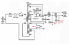
In the power supply, I'd suggest these changes. The CL90 is optional.

mag ps.png

Specifically I'd remove the hum pot and replace it with two 100 ohm 2 watt metal film resistors and wire up as shown. The hum pot won't reduce hum any more than the configuration shown above AS LONG AS you follow good grounding principles when you wire it up. Note also I've drawn a wire between the center tap of the high voltage secondary winding and the negative terminal of the first cap in the power supply. There should be no other connections between those two points because that wire carries high ripple current. and is noisy.

A three prong plug is not necessary, but if you want to add one, connect the ground of the plug to the negative side of the first cap in the power supply (i.e., to the same point as the center tap of the high voltage secondary winding).

The bucking connection on the primary will require a trial and error approach to get it wired correctly (since both leads are labeled brown, you can't distinguish orientation). One orientation will "boost" and the other orientation will "buck." You can determine which orientation produces the "bucking" action by connecting it in a randomly chosen orientation, apply 120V wall voltage, and then measure the AC voltage between the center tap and one of the ends of the high voltage winding. Note the voltage, then reverse the bucking connection and see if the measured voltage goes down or up. You want it in the orientation that delivers the lowest voltage as measured between the center tap and the end chosen.
 
There is one addition I forgot to mention in the audio amp section, that is the addition of screen stopper resistors. These are the 100 ohm resistors shown in red. They should go on both channels. These resistors will keep the screens from oscillating parasitically under certain conditions. These should be 1 watt types if using carbon film or two watt types if using metal film (only because 1 watt metal film resistors are so small they are hard to handle).

upload_2019-11-11_21-41-57.png
 
Another point to bring up is about the ground wiring. I believe the original wiring used numerous points on the chassis itself as ground connect points. But since you are going to rewire the entire amp from scratch (I believe), there is no reason to keep the original grounding scheme. In fact you can improve upon it substantially by following a few simple steps. These steps add a little time and a bit more complexity but will create a very quiet amp when finished (assuming you use good tubes).

1. Use a bus-star combo grounding scheme. This is essentially a bus (a length of wire or multiple lengths of wire strung together end to end) starting at the center tap of the high voltage winding of the power transformer on one end and concluding at the grid ground reference location of the input tube on the other end, with star connect points coming off the bus at the points along the bus where needed.
2. You can think of the bus as having a noisy end on the power transformer CT connection side, and a quiet end at the grid gound reference point for the input tube on the other end. You do not want to connect noisy stages to the quiet end of the ground bus, and vice versa. You also do not want to connect anything on the section of the bus between the power transformer CT and the first cap in the power supply. This section of the bus caries a lot of ripple current so nothing should be connected between those two points.
3. The ground bus is connected to the chassis at one point only. This point is where it will produce the quietest results, and is usually tied in on the ground bus at the negative terminal of the first filter cap (i.e., the reservoir cap) and usually tied to the chassis near the power inlet to the amp.
4. If using a three prong plug, the ground of the plug should connect to the same point on the chassis as the bus ground is connected to the chassis. If using a two prong plug I'm not sure there is a single optimal connect point that is the same for every amp. It probably differs based on the amp you're building. I usually leave that to the very end (using an aligator clip to connect that ground temporarily to find the quitest place).
5. Hum can be introduced when there is a voltage potential difference along the ground system between the cathode ground reference of the stage and the grid ground reference for the same stage. To avoid this, make these two ground reference points exactly the same point, so that no voltage potential difference can possibly exist there. That forms a local star, which is then connected to the bus at the appropriate end of the bus (output stage--near the noisy end, input stage near the quiet end).

Here is a picture I created several years ago showing a bus/star combo grounding scheme for an amp I built. I've made the background B/W, then used green to indicate the bus, yellow to indicate the star sub-ground networks, and pink circles to show the connect points of the star sub-grounds into the bus. I've labeled the noisy end and the quiet end of the bus.

Hopefully this will be of some help as you sort out how to wire the grounds for your amp.

(Note I built the amp pictured below probably 6 years ago before I figured out all the steps listed above. Eagle-eyed observers will call out two items: 1) the connect point from the bus to the chassis occurs at the quiet end of the bus, and yet I'm using a three prong inlet. That's not the location I would connect the bus ground to the chassis today-- if I were to build that same amp again, and 2), the RCA input jack sleeves are not grounded at the same location as the cathode ground reference for the first stage. Again, that's not where I would ground the RCA inlets today. But in any case, my purpose for showing this picture is for you to get a general idea of what the bus/star grounding scheme looks like.)

Ground system - Copy.JPG
 
Last edited:
Thanks so much for all the help! I have managed to get the PT cleaned up, painted and remounted. It is wired back up and the bucking mod performed. Turned out to be easier then I thought it would be thanks to your tips. I went through the amp checking resistors and found that probably 90% of them had drifted at least 20%+ to over 80%. I will be replacing all of them. This is the list of items ordered so far. I have one more order to put in and its off to the bench. Not all these parts are for this amp. I will keep reading as I go. Feel free to keep any ideas coming.

Thanks again!


Capacitor - Mallory, 630V, 150s, Axial Lead
  • Capacitance: .047 µF
C-MD047-630 $1.55 $6.20
4 × Capacitor - 630V, Metal Film, Tubular
  • Capacitance: .0033 µF
C-TD0033-630 $0.60 $2.40
4 × Capacitor - 600V, 716P Series, Polypropylene
  • Capacitance: .047 µF
C-PD047-600 $1.50 $6.00
4 × Capacitor - 600V, 716P Series, Polypropylene
  • Capacitance: .0033 µF
C-PD0033-600 $0.95 $3.80
4 × Capacitor - 25V, 25µF, Axial Lead Electrolytic C-ET25-25 $0.25 $1.00
1 × Terminal Strip - 3 Lug, 2nd Lug Common, Horizontal P-0301H $3.75 $3.75
1 × Terminal Strip - 5 Lug, 3rd Lug Common, Horizontal P-0501H $4.75 $4.75
2 × Binding Post - PCB Type, Gold Plated
  • Color: Black
S-H266B $2.50 $5.00
1 × Capacitor - 450V, Radial Lead, Electrolytic
  • Capacitance: 10 µF
C-ETR10-450 $1.00 $1.00
1 × Capacitor - 450V, Radial Lead, Electrolytic
  • Capacitance: 22 µF
C-ETR22-450 $0.60 $0.60
1 × Capacitor - 450V, Radial Lead, Electrolytic
  • Capacitance: 33 µF
C-ETR33-450 $1.10 $1.10
1 × Capacitor - 450V, Radial Lead, Electrolytic
  • Capacitance: 47 µF
C-ETR47-450 $1.25 $1.25
1 × Antique Electronic Supply Catalog #29 (2018) CATALOG-AES $0.00 $0.00
2 × Resistors - 1 Watt, Metal Oxide, Power
  • Resistance: 47 kΩ
R-E47K $2.30 $4.60
2 × Resistors - 1 Watt, Metal Oxide, Power
  • Resistance: 470 kΩ
R-E470K $2.30 $4.60
1 × Resistors - 1 Watt, Metal Oxide, Power
  • Resistance: 3.3 kΩ
R-E3D3K $2.30 $2.30
1 × Resistors - 1 Watt, Metal Oxide, Power
  • Resistance: 220 Ω
R-E220 $2.30 $2.30
2 × Resistors - 1 Watt, Metal Oxide, Power
  • Resistance: 470 Ω
R-E470 $2.30 $4.60
1 × Resistors - 1 Watt, Metal Oxide, Power
  • Resistance: 2.2 kΩ
R-E2D2K $2.30 $2.30
1 × Resistors - 1 Watt, Metal Oxide, Power
  • Resistance: 22 kΩ
R-E22K $2.30 $2.30
1 × Resistors - 1 Watt, Metal Oxide, Power
  • Resistance: 6.8 kΩ
R-E6D8K $2.30 $2.30
1 × Resistors - 1 Watt, Metal Oxide, Power
  • Resistance: 5.1 kΩ
R-E5D1K $2.30 $2.30
1 × Resistors - 1 Watt, Metal Oxide, Power
  • Resistance: 100 kΩ
R-E100K $2.30 $2.30
2 × Binding Post - PCB Type, Gold Plated
  • Color: Red
 
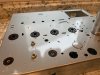
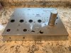
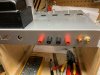
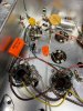
Have been spending a fair amount of time on the unit the last few days. I wasn't happy with some of the marks/tarnish on the bare chassis so I prepped it and shot it with hammered silver. Think it came out pretty nice. A bunch of parts also arrived so I started replacing them section by section. Took my time and lots of before pics to help guide me. I'm still waiting on a few more from Mouser. The leads on some of the resistors were shorter than others so I had to get creative. If anyone sees an issue with how I did it please let me know. Here are some pics. I also updated to speaker jacks to a better quality.

The large resistor on the cap section is a 100K ohm if I am correct? Watt wattage would it be? Sorry if it's a dumb question. With the hum pot removed is it still needed? I have all separate caps to replace the can style but will leave it up top for looks.

Thanks!
 

Attachments

  • IMG_1997.JPG
    IMG_1997.JPG
    81.4 KB · Views: 37
  • IMG_1994.JPG
    IMG_1994.JPG
    113.6 KB · Views: 34
  • IMG_1998.JPG
    IMG_1998.JPG
    107.6 KB · Views: 37
  • IMG_2004.JPG
    IMG_2004.JPG
    71.9 KB · Views: 37
I have another question. Pictured is the original speaker terminal strip. Am I correct in my thought that both negative speaker jacks will get wired to the tab circled in black and the red jacks will get wired to those circled in red?
Also what value caps should I replace those circled in yellow with? I am assuming .001K for both? I have replaced the resistors with new metal films of the same value but am stuck on the cap values. Thanks!IMG_1909.JPG
 
Back
Top Bottom