• The move to the new server is done. There are some software and database maintenance updates in process. This has us passing the hat around to help out. We appreciate any donations. Seriously, even a dollar helps. The payment page may be found here - https://www.audiokarma.org/support.html

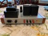
Mag 175-67 rebuild. Questions, Questions........

100k resistor is 1watt
Those ceramic caps are your feedback network. They are different because of the use of the original balance pot.
Replace them both with 1000pf per upper section in schematic but be prepared to tinker with the value to tame amp oscillations.
Looking very good!
 
Thanks for the reply! I will hopefully have this all wired up by the morning. The rest of my order from Antique electronics showed up yesterday and we are on a moratorium at work so I should have some time to go over it. I have attached a shot with possible OPT covers I am toying with. They are small Pringles chip containers lol. Also have some tins from some Twinings tea I am going to spray up tonight with black krinkle paint and see how they look.
 

Attachments

  • IMG_2038.JPG
    IMG_2038.JPG
    86.2 KB · Views: 39
  • IMG_2026.JPG
    IMG_2026.JPG
    77 KB · Views: 40
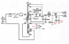
There is one addition I forgot to mention in the audio amp section, that is the addition of screen stopper resistors. These are the 100 ohm resistors shown in red. They should go on both channels. These resistors will keep the screens from oscillating parasitically under certain conditions. These should be 1 watt types if using carbon film or two watt types if using metal film (only because 1 watt metal film resistors are so small they are hard to handle).

View attachment 1670437

@kward I can simply lift the red wire from the OPT that's on pin 4 of both channels, solder the resistor to the pin and the red wires from the OPT's to each resistor correct?

Also, in the schematic I have attached you recommended the 2 100 ohm resistors from the green wires on the transformer to ground. On my unit I have a green wire and a green/white . Green goes to pin 2 and the g/w goes to pin 7.Can I simply take the 2 100 ohm resistors and put one leg on pin 2and other leg to ground and the same on pin 7?

Thanks again for all the help!mag ps.png
 
@kward I can simply lift the red wire from the OPT that's on pin 4 of both channels, solder the resistor to the pin and the red wires from the OPT's to each resistor correct?
That’s essentially correct. Try to find a free solder lug nearby you can use to make the other end connection to the screen voltage wire.
Can I simply take the 2 100 ohm resistors and put one leg on pin 2and other leg to ground and the same on pin 7?
Yup. Wherever is most convenient.
 
@kward I'm down to I think my last few questions lol. Again I can't thank you enough for your help. I have attached a picture of the hum pot. If I'm understanding it the yellow wire will get soldered to the lug on the cap correct? Its attached via the center terminal of the pot so I'm assuming if the pot is gone it just gets soldered to the lug. Where would I then attach the green and blue wires that were attached to the pot? Sorry if this seems like a dumb question. I have attached a picture of the humpot.

I actually may have one more question in regards to the center tap wire you mentioned in a post above but I will post that once I get through the hum pot wiring. Baby steps lol.

Thanks again!IMG_1937.JPG
 
I think you may have answered that in your above post. I can simply solder one resistor to the blue wire and other end to ground? Same with the green wire correct? Yellow to the lug on the capacitor?
 
If I'm understanding it the yellow wire will get soldered to the lug on the cap correct?
That’s correct, but you could also connect the junction of the two 100 ohm resistors to the yellow wire if you wanted, instead of to ground, leaving the connection to the cap in tact as shown in the picture.

In the original circuit, the filament circuit is DC biased (and therefore referenced to ground) by the voltage on the cathodes for additional hum control. In the proposed changes I drew, the filament circuit is simply grounded to circuit ground through those two 100 ohm resistors. In other words, if the chassis is not used as the circuit ground the hum pot adds no realizable value.
 
Last edited:
Isn't DC biased filament type better for tube health, compared to simple 0v ground reference through resistors?
6V6 may not be affected but what about 12AX7 drivers? That was DG recommended upgrade to Fisher 400/500/800 as a part of noose revisit update.
 
All cathodes in the Magnavox amp being built sit just a few volts above ground, so there is marginal benefit of up-biasing the filaments. The benefit gained by up-biasing the filaments is the "reverse bias" condition it creates between heater and cathode, so that in a case of a tube with marginal heater insulation, current cannot flow from the filament to the cathode and introduce hum. That appears to have been the thinking in the original design of this amp.

If memory serves, the power amp sections of the Fisher models you mention have the inverter triode's cathode sitting at something like 100V DC above ground potential. In this scenario, in order to stay away from the max heater-cathode limits, and to alleviate a bit the stress on the heater insulation, it's wise to up-bias the filaments by "some appropriate" amount. There are two limits that must be managed when biasing filaments: the "heater positive with respect to cathode" limit and the "heater negative with respect to cathode" limit. You don't want to up-bias too far or you will run into the heater positive with respect to cathode limit for those cathodes that run just a few volts above ground. So what is usually done is to "split the difference" somehow. What I usually do is divide the highest voltage cathode by 4 (that turns out to be about 25V in situations like the Fisher models mentioned) and bias up all filaments that run on that filament secondary winding by that amount. Thus the tubes that run their cathodes a few volts above ground run at approximately +25V heater positive respect to cathode, while the phase inverter triode runs at approximately -75V heater negative respect to cathode. For a 12AX7, those voltages are well within range of both of the heater/cathode limits.

Before you bias the filaments though, it's always good to validate the heater-cathode ratings (both directions) to ensure you are well within the limits.

 
Good morning guys. It's finished! Well not finished but currently playing some jazz/blues favorites through my KG4's. To my ears and my sons ears it sounds, as he put it, "Flippin' Awesome!" lol. I agree that to my 52 yr old ears it sounds pretty sweet. That being said I have a few issues/questions...

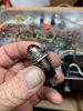
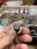
We were throwing out a bunch of NOS stock at work and grabbed a few of these gorgeous vintage power lamps/indicators. Rated for 125v ac I thought they would be perfect for use with the amp. I have attached a few pictures of it and the bulb used. I CANNOT for the life of me figure out why but if I put the lamp inline with the power switch the amp refuses to power up. The bulb lights and I have 117 volts up to one side of the lamp. After that its like 7 volts AC. I tried 3 different bulbs all with the same effect. Take the bulb out, wire it through just the switch and it works perfectly. ?? I went and ordered some quality LED based pilot lights from Amazon, rated for 125v AC and strangely the same thing happens with them. Could it be because I am running a thermistor? I don't see why that would be but reaching for an answer.

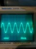
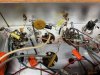
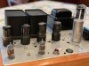
The second "Issue" I am seeing is in the images from my scope. The 1Khz sine wave looks balanced and smooth to my eyes. As I don't own a function/signal generator right now I am feeding this signal via my ipad using a tone generator app. When I switch to square wave this is where things get, if I have been reading correctly, REAL ugly. I am seeing what I think is horrible ringing. Is my thought correct? What would cause this and how can I correct it? I have swapped rectifier tubes as well as preamp tubes. I have not tried swapping the output tubes yet. The current tube layout is a Westinghouse 5U4G that tested at 2800/2900, a quad matched set of NOS GE/Kenrad 6V6's and 2 RCA Black Plate 12AX7's. It's weird because to my ears the amp sounds wonderful but from what I am reading ringing can be bad for tweeters. If it means anything I am using a 2845 scope, 10X probe with ground to chassis and probe to speaker outputs. I have attached a picture of the wiring/feedback for the 12ax7's.

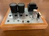
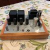
Other than that I am pretty happy with the way it turned out. More surprising was my wife saying that it was the "prettiest amp" shes seen me own lol. The chassis was lightly sanded and wiped with prepsol before spraying with Krylon hammered silver. The base is a piece of 90 yr old cherry stock I have that was cut down and glued together, sanded and finished with 6 coats of Danish Oil sanding with 400 grit between coats. The OPT covers are Twinings tea tins sprayed with VHT Wrinkle paint and baked in an oven for 2 hours at 175.

Thanks for any help!

Bobby
 

Attachments

  • IMG_2075.JPG
    IMG_2075.JPG
    44.8 KB · Views: 37
  • IMG_2076.JPG
    IMG_2076.JPG
    44.7 KB · Views: 33
  • IMG_2077.JPG
    IMG_2077.JPG
    51.9 KB · Views: 32
  • IMG_2074.jpg
    IMG_2074.jpg
    43.6 KB · Views: 33
  • IMG_2070.JPG
    IMG_2070.JPG
    47.9 KB · Views: 32
  • IMG_2078.jpg
    IMG_2078.jpg
    123.4 KB · Views: 37
  • IMG_2079.JPG
    IMG_2079.JPG
    90.1 KB · Views: 36
  • IMG_2081.jpg
    IMG_2081.jpg
    83.1 KB · Views: 36
  • IMG_2083.JPG
    IMG_2083.JPG
    97.3 KB · Views: 34
We were throwing out a bunch of NOS stock at work and grabbed a few of these gorgeous vintage power lamps/indicators. Rated for 125v ac I thought they would be perfect for use with the amp. I have attached a few pictures of it and the bulb used. I CANNOT for the life of me figure out why but if I put the lamp inline with the power switch the amp refuses to power up. The bulb lights and I have 117 volts up to one side of the lamp. After that its like 7 volts AC
Using bulb in series will not work. You are trying to power the amp through the tiny bulb filament. One leg should go to Neutral and second connected to switch output. Then your bulb will light up when switch is "ON"
 
The second "Issue" I am seeing is in the images from my scope. The 1Khz sine wave looks balanced and smooth to my eyes. As I don't own a function/signal generator right now I am feeding this signal via my ipad using a tone generator app. When I switch to square wave this is where things get, if I have been reading correctly, REAL ugly. I am seeing what I think is horrible ringing. Is my thought correct?
Are you doing scope tests with speakers connected or dummy loads. Using speakers as a load may cause it to look a lot worse then it is. Also, check your input signal with the scope just to make sure it is not what your amp is trying to amplify
 
All cathodes in the Magnavox amp being built sit just a few volts above ground, so there is marginal benefit of up-biasing the filaments. The benefit gained by up-biasing the filaments is the "reverse bias" condition it creates between heater and cathode, so that in a case of a tube with marginal heater insulation, current cannot flow from the filament to the cathode and introduce hum. That appears to have been the thinking in the original design of this amp.

If memory serves, the power amp sections of the Fisher models you mention have the inverter triode's cathode sitting at something like 100V DC above ground potential. In this scenario, in order to stay away from the max heater-cathode limits, and to alleviate a bit the stress on the heater insulation, it's wise to up-bias the filaments by "some appropriate" amount. There are two limits that must be managed when biasing filaments: the "heater positive with respect to cathode" limit and the "heater negative with respect to cathode" limit. You don't want to up-bias too far or you will run into the heater positive with respect to cathode limit for those cathodes that run just a few volts above ground. So what is usually done is to "split the difference" somehow. What I usually do is divide the highest voltage cathode by 4 (that turns out to be about 25V in situations like the Fisher models mentioned) and bias up all filaments that run on that filament secondary winding by that amount. Thus the tubes that run their cathodes a few volts above ground run at approximately +25V heater positive respect to cathode, while the phase inverter triode runs at approximately -75V heater negative respect to cathode. For a 12AX7, those voltages are well within range of both of the heater/cathode limits.

Before you bias the filaments though, it's always good to validate the heater-cathode ratings (both directions) to ensure you are well within the limits.
Thanks Kevin. A lot to study. It all makes sense when I read it but to keep it in memory so this info stands out and raises the flag when needed - that requires your type of experience.
 
Congratulations on getting a working amp! In addition to the suggestions grindfix has provided, make sure the feedback cap is installed and is of the correct value.
 
Using bulb in series will not work. You are trying to power the amp through the tiny bulb filament. One leg should go to Neutral and second connected to switch output. Then your bulb will light up when switch is "ON"

Holy crap talk about a brain fart! Never thought of that ‍♂️ Electronics 101. But now I am trying to figure out the layout. Can I run the lamp parallel to the switch? Pissed I can’t wrap my head around this simple thing.
 
Last edited:
Are you doing scope tests with speakers connected or dummy loads. Using speakers as a load may cause it to look a lot worse then it is. Also, check your input signal with the scope just to make sure it is not what your amp is trying to amplify

Speakers are disconnected. Didn’t think of checking the source. I’ll do that tonight.
 
Congratulations on getting a working amp! In addition to the suggestions grindfix has provided, make sure the feedback cap is installed and is of the correct value.

Thanks Kevin! Could t have done it without your input and patience. I replaced the caps in the feedback circuit with Mallory’s with the stock values.

Next plan is the paraphrase mod Are you ready? Lol
 
Speakers are disconnected. Didn’t think of checking the source. I’ll do that tonight.
Big no, no, no with tube gear. Have to have proper load on transformers. Do not turn it on without loads and do not do any signal testing without load
 
Back
Top Bottom