• The move to the new server is done. There are some software and database maintenance updates in process. This has us passing the hat around to help out. We appreciate any donations. Seriously, even a dollar helps. The payment page may be found here - https://www.audiokarma.org/support.html

Mag 175-67 rebuild. Questions, Questions........

That is no problem. Check your input signal signature and post it if it's not really square. If it is proper looking - you have some frequency compensation to do. A lot of that was covered in my build here:
https://audiokarma.org/forums/index.php?threads/magnavox-amp-185-question.880953/

First, make sure your v/div center switch is turned to "CAL". Otherwise, scope is not showing correct voltages. Set your probes to x1 and adjust your scope to suitable display to show 1 watt of output into 8ohm load. That is approximately 4vac peek to peek. If you have a 2v/div setting your 1watt will take 2 vertical divisions between positive and negative peeks. Recheck your square wave at 1 watt of output. Hopefully it's not that ugly.
 
Another thing I would do. Take your probe to calibration point on the face of the scope. It should say "cal 5vpip" or something like that. Adjust your p/div to see 2.5v up and 2.5v down. That will tell you if your scope is properly set to display 1watt of output. Higher wattage will look really ugly with squares.
 
I think it would be a good idea to take some measurements before you convert to the floating paraphase in order to establish a baseline for the amp. You can use the baseline as a measure of stock performance so that after you convert, you know if you are worse or better than stock performance. Hopefully the paraphase will get you somewhat better performance.

These tests are relatively easy to do with a signal generator, a scope, and two large wattage load resistors.

1. Test stability of the amp at both HF and LF.
2. Measure input sensitivity.
3. Measure frequency response and power bandwidth
4. Measure hum and noise at the speaker terminals.
5. Amount of feedback applied.
6. Output resistance--to establish the damping factor.

Also I would listen to the amp for a while (a week or so) before making any changes so you get a feel for how it sounds. Anyway these are ideas...you can go faster if you want if the amp is stable, but I think it's good practice to at least take baseline measurements before proceeding. If you have those tools listed above, you can do all of the above measurements in a few hours or less. If you don't have a signal generator, you can use your iPad if it will generate test signals from 20 Hz to 20 KHz, but you might need to pipe the output of the iPad into an outboard preamp, which then feeds the power amp, in order to obtain a drive signal large enough to drive the amp to full power.

We can walk you through the procedure for each test once you are ready.
 
Output impedance measurement requires running signal with open output. In my case it was absolutely no problem but may not be the case in this build. Be ready to turn power off if amp breaks out in oscillation. When THAT starts - you can't miss it on the scope display. My amp was unstable into capacitor only loads but was perfectly happy with open output.
Frequency tuning that you may have to do is going to affect stability and frequency response. Without experience that some of this forum members have, finding reasonable compromise may take long time tinkering but it is absolutely necessary before you put amp into service, even if you think it sounds really good.
 
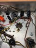
Wound up working over the holiday but managed a little time last night to work on the amp. I had been thinking about the old can cap and it's condition. Even thiough I tested it I guess, in the back of my brain I didn't trust myself lol. SO I dove in and replaced the can cap with all new electrolytics. I left the original in place for aesthetics. Once I laid it out on paper so I could grasp it it wasn't hard. Came out decent I think. And yes I know the one cap was wired backwards. Thankfully caught it during the once over before powering the unit up. Phew!

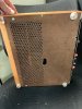
I also tested the output from my Ipad using the signal gen software and to my surprise the square wave was as ugly as I saw from the amp. Thanks to @grindfix for suggesting I test it. Now I guess I need to pick up a cheap, used signal gen. But I felt better knowing it wasn't the amp that was that ugly. @kward I would like to do the testing you wrote about but will have to wait I guess till I can get a solid signal to the amp first. Any recommendations on a decent but not crazy priced signal generator? I also reused a small piece of the back of the console radio my magnavox 8601 amp came from as a cover for the bottom.

Thanks again and hope the holiday was enjoyable.
 

Attachments

  • IMG_2104.JPG
    IMG_2104.JPG
    73.4 KB · Views: 28
  • IMG_2105.JPG
    IMG_2105.JPG
    73.4 KB · Views: 27
@kward recommended BK 4017A I got new on eBay works really well.

Isn’t it funny that Home Depot sells those bumpers in clear but not in black?

It's crazy because they have clear, light tan and white in my local HD. Would love to have black. I'll have to keep an eye out for one of the BK's.
 
Any recommendations on a decent but not crazy priced signal generator?
Right, a used BK 4017A is not that expensive, and is a solid generator. Not the top of the line or anything like that but it works well for what it does. It's still in production even.
 
H
It's crazy because they have clear, light tan and white in my local HD. Would love to have black. I'll have to keep an eye out for one of the BK's.
Pretty good post, lots of great info. I'm compiling my parts list and hope to have it ordered
Thanks so much for all the help! I have managed to get the PT cleaned up, painted and remounted. It is wired back up and the bucking mod performed. Turned out to be easier then I thought it would be thanks to your tips. I went through the amp checking resistors and found that probably 90% of them had drifted at least 20%+ to over 80%. I will be replacing all of them. This is the list of items ordered so far. I have one more order to put in and its off to the bench. Not all these parts are for this amp. I will keep reading as I go. Feel free to keep any ideas coming.

Thanks again!


Capacitor - Mallory, 630V, 150s, Axial Lead
  • Capacitance: .047 µF
C-MD047-630 $1.55 $6.20
4 × Capacitor - 630V, Metal Film, Tubular
  • Capacitance: .0033 µF
C-TD0033-630 $0.60 $2.40
4 × Capacitor - 600V, 716P Series, Polypropylene
  • Capacitance: .047 µF
C-PD047-600 $1.50 $6.00
4 × Capacitor - 600V, 716P Series, Polypropylene
  • Capacitance: .0033 µF
C-PD0033-600 $0.95 $3.80
4 × Capacitor - 25V, 25µF, Axial Lead Electrolytic C-ET25-25 $0.25 $1.00
1 × Terminal Strip - 3 Lug, 2nd Lug Common, Horizontal P-0301H $3.75 $3.75
1 × Terminal Strip - 5 Lug, 3rd Lug Common, Horizontal P-0501H $4.75 $4.75
2 × Binding Post - PCB Type, Gold Plated
  • Color: Black
S-H266B $2.50 $5.00
1 × Capacitor - 450V, Radial Lead, Electrolytic
  • Capacitance: 10 µF
C-ETR10-450 $1.00 $1.00
1 × Capacitor - 450V, Radial Lead, Electrolytic
  • Capacitance: 22 µF
C-ETR22-450 $0.60 $0.60
1 × Capacitor - 450V, Radial Lead, Electrolytic
  • Capacitance: 33 µF
C-ETR33-450 $1.10 $1.10
1 × Capacitor - 450V, Radial Lead, Electrolytic
  • Capacitance: 47 µF
C-ETR47-450 $1.25 $1.25
1 × Antique Electronic Supply Catalog #29 (2018) CATALOG-AES $0.00 $0.00
2 × Resistors - 1 Watt, Metal Oxide, Power
  • Resistance: 47 kΩ
R-E47K $2.30 $4.60
2 × Resistors - 1 Watt, Metal Oxide, Power
  • Resistance: 470 kΩ
R-E470K $2.30 $4.60
1 × Resistors - 1 Watt, Metal Oxide, Power
  • Resistance: 3.3 kΩ
R-E3D3K $2.30 $2.30
1 × Resistors - 1 Watt, Metal Oxide, Power
  • Resistance: 220 Ω
R-E220 $2.30 $2.30
2 × Resistors - 1 Watt, Metal Oxide, Power
  • Resistance: 470 Ω
R-E470 $2.30 $4.60
1 × Resistors - 1 Watt, Metal Oxide, Power
  • Resistance: 2.2 kΩ
R-E2D2K $2.30 $2.30
1 × Resistors - 1 Watt, Metal Oxide, Power
  • Resistance: 22 kΩ
R-E22K $2.30 $2.30
1 × Resistors - 1 Watt, Metal Oxide, Power
  • Resistance: 6.8 kΩ
R-E6D8K $2.30 $2.30
1 × Resistors - 1 Watt, Metal Oxide, Power
  • Resistance: 5.1 kΩ
R-E5D1K $2.30 $2.30
1 × Resistors - 1 Watt, Metal Oxide, Power
  • Resistance: 100 kΩ
R-E100K $2.30 $2.30
2 × Binding Post - PCB Type, Gold Plated
  • Color: Red
thanks for posting what you bought. I’m coming up with my own list and may use this compared to mine. So you didn’t go with .1 and .0075 for your coupling caps?
I’ve read almost too much info on this build and it’s starting to make me doubt what I should do!

My maggy 8802 was much easier! Somebody on Facebook had just restored theirs and gave me a list of exactly what he ordered. I can do the work, but my decision making skills are piss poor!

Have you changed anything recently or wish you had done something else?
 
Having looked at so many 175 articles here- this one is very good- beginning, middle and end. Thank you.
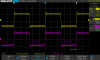
This is my 1 khz square wave - I haven't put in the screen stoppers. Not sure that is needed?SDS00022.png
 
Last edited:
Sounds great- today's odd thing- I am getting bleed from one channel to the other, but not the other way around. I'll look into it.
I saw how hot that 125 ohm 10 watt resistor gets so I put a small, really small fan underneath. 140 degrees with the fan. Still going to put feet on the amp.
IMG_4479.JPG IMG_4481.JPG
 
You don't need a fan. It is running perfectly normal. As far as bleed through is concerned, recheck your work. Also try swapping your 12AX7 tubes.

My Magnavox 175-67 has absolutely no bleed through whatsoever.
 
Back
Top Bottom