• The move to the new server is done. There are some software and database maintenance updates in process. This has us passing the hat around to help out. We appreciate any donations. Seriously, even a dollar helps. The payment page may be found here - https://www.audiokarma.org/support.html

Magnavox 169 BB Output Transformers

Progress report.
The paint and clear coat is drying on the first chassis. It is a black base coat with fireball color shift coat and a 2k clear coat. I'll give it a day or two to cure then I'll build to the schematic @wparks posted in post 11. Once that is done I'll be back so we can figure out the TBD cap and resistor.
What is that color paint you used? I like it!
 
I always throw mine into the big food dehydrator at 100F for overnight so it's not tacky at all- otherwise they can be tacky for days and days.

This is probably putting the cart before the horse, but some notes to think about as you build and approach power-on.

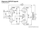
Because we are never 100% sure of the convention used to wind the output transformer, (color codes are not always consistent), I always do a polarity test in open loop with feedback disabled before doing anything with feedback connected. (Or you might get a nasty oscillation). When you first build and power on the amp, have the feedback path disabled as shown in the schematic below. The far end of the TBD feedback resistor (if known) is usually disconnected from the OPT output and grounded- this allows the 6AN8 pentode to see the same DC bias conditions it will later with feedback connected. It's not quite so important in this particular design because the feedback resistor is probably much larger than the 1500+220 ohm cathode resistance, but in some designs the tie to ground is required or the voltage amp won't work properly. Here, you can just leave it and the cap out.

If any of your component values are different than the schematic, let me know, and I will update it to prevent confusion.
First thing, collect all of the voltages in this open loop state so we can evaluate if there are any DC adjustments to be made- I assume the power supply is as indicated in the "Jason's notes" schematic. We will want to see right away the high voltages at the positive terminal of each of the power supply bypass caps. Grab the 6V6 cathodes (pin 8), plates (pin 3) and screens (pin 4). Grab the 6AN8 voltages- pentode plate (pin 6), screen (pin 7) and cathode (pin 9), and triode plate (pin 1) and cathode (pin 3)

To check polarity, I use a ramp waveform like that shown below. Scope this coming right out of the signal generator to see what the input to the amp will look like. When this waveform is right side up, the ramp travels up from lower left to upper right. If you inject this into the input, and the output is the same, it is non-inverted, it's safe to proceed connecting up feedback. If it's inverted (ramping down from upper left to lower right), you can either flip the blue and brown primary leads, or swap the secondary leads, pick one, whichever is easiest.

AMP169_6V6PP_with_Feedback_Disabled.jpg Ramp_Waveform.jpg

From there, at a very high level, we will proceed with:
With 1kHz sine, push the output up to squashing, then clipping, to see if it's symmetrical and well behaved.
With 1kHz sine, measuring open loop gain, and deciding what closed loop gain you want.
Use a ~20K pot to dial in the closed loop gain you selected, to determine what the feedback resistor will be.
Look at the 10kHz square wave response, and choose a feedback compensation cap for proper response.
Again look at maximum power at clipping, verify input amplitude to achieve maximum power
Stability testing- into open output (no load) and with small capacitive only load.
Frequency response at 1 watt, Power Bandwidth at max power minus 1 dB.

 
I tend to struggle with picking paint that will look decent. I think my next one is going to be brown hammertone and the transformer end bells will be gold just for some contrast. Hoping the texture will hide my slightly abused chassis and poor bodywork.

just be aware that with a 2.2M screen resistor, even with a 10M input meter its going to load it down enough that the voltage reading isn't going to be entirely accurate or useful. With stuff like this its generally more useful to just get the plate voltage and if that needs adjusting, tweak the screen resistor accordingly.

if the balance is off, you can change one of those 470K resistors as needed to get it right.
 
What is that color paint you used? I like it!
I used the Kustom Canz line. The Chromacoat Fireball is the color shift. Its a primers, black base, chromacoat, and the 2k clear on top. I did the shoot a layer then let it sit over night. The next evening was the next layer. I also did media blast the chassis.

This is probably putting the cart before the horse, but some notes to think about as you build and approach power-on.
The more info the better. I did not tear apart the other mono block, so I do have a working unit to see how the transformer is wired. My intent was to wire the power supply and test check those voltages before wiring the rest.
 
I did not tear apart the other mono block, so I do have a working unit to see how the transformer is wired.
I think you misunderstand my above comments. Transformers are not identical, and the manufacturers do not follow any standard convention with wire color codes. I have seen many builds where an OPT is swapped, wired exactly the same, and an inversion in the signal path is unintentionally introduced that causes severe oscillation when feedback is connected. This polarity swap will then generate positive feedback instead of negative feedback. Manufacturers do not always know how many signal inversions will normally occur in a particular design, so even if color codes were standard, some designs require a swap.

The polarity check is very quick and easy, and you generally want to start open loop to begin with anyway, to validate functionality of the forward amplifier, and measure open-loop gain before you start complicating the design with negative feedback.

My intent was to wire the power supply and test check those voltages before wiring the rest.
That is a sound strategy, but all of your voltages will run high as they are unloaded. At that point just a low level AC voltage from the variac to make sure nothing is shorted is usually adequate. Same with after it's built and tubes are in place for loading- bring it up slowly, checking to make sure you have some voltage in all the right places. Have the scope watching the output so you can see any oscillation or instability as soon as it starts happening.
 
^^ can confirm, brown and blue are fairly standard, but which end of the winding they actually hook to is not. I've run into this with SE transformers too, my 6bq5 amp has red to the plates and blue to B+ to get phasing correct. Stock was opposite.
 
Tonight I got some wiring done. That has led to a question.

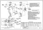
On the attached schematic, in the power supply section, R18 and R19 center point goes to pin 8 on the output tubes. Is that still correct with the schematic @wparks provided?
 

Attachments

  • Amp169- 170_Pg-4 with Jasons Mods 2.jpg
    Amp169- 170_Pg-4 with Jasons Mods 2.jpg
    103.2 KB · Views: 29
  • PXL_20260930_232929393.jpg
    PXL_20260930_232929393.jpg
    167.4 KB · Views: 20
  • PXL_20260930_232932961.jpg
    PXL_20260930_232932961.jpg
    102.4 KB · Views: 23
  • PXL_20260930_233005111.jpg
    PXL_20260930_233005111.jpg
    185.7 KB · Views: 35
I would, but you can also run it to ground if you prefer. Going to pin 8 gives some DC on the heaters which tends to make it quieter. There isn't any significant heater-cathode voltage on anything here so its not a big problem if it did go to ground though.
 
This morning I was able to grab some voltages before work. Just be sure I have it correct, these are with Pin 9 on 6AN8 also connected to ground and not the positive tap off the OPT. Power supply is wired to the schematic in post #27. After work I'll figure out the OPT polarity. How does this look for voltages?

These voltages are on the positive side of the caps. All voltages are VDC.
40uF - 335
30uF - 338
10uF - 225

6v6
Pin 8 - 21 & 21
Pin 3 - 331 & 335
Pin 4 - 338 & 338

6AN8
Pin 1 - 17
Pin 3 - 0
Pin 6 - 34
Pin 7 - 9
Pin 9 - 0
 
pins 1 and 9 on the 6AN8 need to go to the 6.3 vac heater line that is going to 2 and 7 on the 6V6 tubes.

Honestly none of the voltages on the 6AN8 look right to me. 3 and 7 are definitely wrong, 3 could be right, not sure. Its not as wrong but without plate voltage it doesn't really matter. This won't be caused by the heater connection.

6V6 volages look reasonable.
 
pins 1 and 9 on the 6AN8 need to go to the 6.3 vac heater line that is going to 2 and 7 on the 6V6 tubes.
I'm confused by this statement. The data sheet says pin 4 & 5 are the heater and that's how the original is wired.
 
you're right, apparently google spit out some BS when I looked up the pinout the first time. I thought that sounded odd, should have gone with my instincts. An actual datasheet is authoritative.

1790949971939.png

either way, the plate voltages look way too low on this.
 
I really need to draw a better power supply schematic for this project. Is this amp currently running the stock OPT, or do you have the OT19PP-DYN35 transformer on there? Are you running Ultra Linear, or are those taps tied off?

OK- Can you clarify how you have the feedback tied off- you say pin 9 of the 6AN8 is tied (directly?) to ground? I would disconnect that. If there were a feedback resistor in place (instead of TBD), it would like be much larger than the 220 ohm plus 1500 ohm resistors that are currently providing the cathode path to ground, and tying that far end of the feedback resistor to ground would preserve the exact biasing the pentode will have during (feedback enabled) operation, but here I would leave it open and just have the 220 and 1500 as it's bias resistor. Can you confirm pin 9 is actually tied to ground?

The high voltages look good.
40uF - 335 (Rectifier cathode or "first cap" or B+)
30uF - 338 (After the choke, or "second cap" or Screen Supply)
10uF - 225 (After 100K dropping resistor, Pre-Amp supply)
But I doubt the voltage at the 30uF would be higher than that of the 40uF (voltage after the choke being higher than before the choke) so you might check this, but to a first order these look REALLY good.

The 6V6 voltages look great (but with same inversion between B+ and screen voltages.)
6v6
Pin 8 - 21 & 21 (cathodes)
Pin 3 - 331 & 335 (plates)
Pin 4 - 338 & 338 (screens)
21V across a 270 ohm shared cathode resistor indicates 78mA combined cathode current, or roughly 39mA each 6V6. I'm guessing that's about 35mA of plate current, so your plates are dissipating (335-21)*.035 = 11W. Not bad. Good place.

On the 6AN8- I need to take this with a big grain of salt if pin 9 is grounded, as it appears to be- the pentode won't be biased correctly, so the plate (pin 6) will be too low, as it appears to be about half of what it should be.
6AN8
Pin 1 - 17
Pin 3 - 0
Pin 6 - 34
Pin 7 - 9
Pin 9 - 0

Don't worry about trying to measure pin 7 (screen). As @gadget73 indicated it's a high impedance node that probably won't measure correctly. But, we don't really need to know it, we judge whether it's good based upon the plate voltage which gives us bias current.
Even with pin 9 grounded, we CAN look at the triode section- What did pin 2 measure? It should be at ~0V. The cathode of this triode (pin 3) should be over 1V, but it's plate (pin 1) looks to be roughly correct at 17V (compared to the "Jasons Notes" schematic of 20V.)

So- Great work so far! Check the power supply, check pin 9 of the 6AN8, and shoot us some more voltages. Next step will be to pipe a signal through for the polarity check, see how the signal through it looks, perhaps measure open loop gain, see how maximum power looks and clipping behaviors (symmetrical?)

AMP169_6V6PP_with_Feedback_Disabled.jpg Jasons_Power_Supply.jpg
 

Attachments

  • AMP-169.pdf
    AMP-169.pdf
    399.7 KB · Views: 2
  • Amp169- 170_Pg-4 with Jasons Mods 2.jpg
    Amp169- 170_Pg-4 with Jasons Mods 2.jpg
    103.2 KB · Views: 6
I really can't believe the factory schematic calls for 20 volts at the plate of the triode. I would want that higher to make sure its got clean output voltage swing. Math checks out, thats the voltage you get at a half milliamp based on cathode volts / cathode resistor but yikes.
 
I know right- but it's a medium-mu triode (20) like a 12AU7. I thought about that- for console use they probably did not crank the output power to the point where swing room was a problem. As a classical paraphase, the plate resistor could always be smaller for the inverter so long as it has sufficient gain, and the input amplitude could be adjusted up with the divider off the plate of the voltage amplifier to keep the output symmetrical. But here, I am not as sure. Do you think we can drop the plate resistor to get more swing room? (and maybe rebias?) I also think we could try a bypass capacitor across the 2200 ohm cathode resistor to help spin the gain up if we did. If it were mine, I think I would want to be looking at 6V6 grid signals and maybe distortion to see what tweaks we could make.
 
Tonight I got some wiring done. That has led to a question.

On the attached schematic, in the power supply section, R18 and R19 center point goes to pin 8 on the output tubes. Is that still correct with the schematic @wparks provided?
That Hammond inductor blemishes the look; can that be hidden underneath? Either that, or make a cover for it.
 
Do you think we can drop the plate resistor to get more swing room? (and maybe rebias?) I also think we could try a bypass capacitor across the 2200 ohm cathode resistor to help spin the gain up if we did.
should be an option. I was thinking smaller plate resistor and probably wind the current up some. Cap to restore some gain wouldn't hurt either, and will help offset the loss from the smaller plate resistor. probably need to bump the 100k in the power supply feeding that node but thats not really a problem either.

In theory, 20v of plate can get you 40 volts peak to peak, in reality we know its not going to pull all the way down to zero volts. With the 6V6 tubes idling at 21v, I would think that means the inverter is going to run out of voltage swing before the output tubes quite get to full power. Tubes tend to get pretty non-linear as they approach saturation anyway so even if it is enough, its got no sort of headroom.
 
I think this is an excellent strategy to pursue. I don't think I want to start tweaking the schematic yet though- Let's get the pentode in good shape and get some signal through it- Perhaps see what @Rudiger wants to do with it. There is a lot of room for improvement if he's up for the scope work :thumbsup:
 
Alright I will attempt to answer all the questions. Lets start with the OPT. I have the OT19PP-DYN35 installed. Attached are the scope pictures. Yellow is amplifier output and blue is input. One is a sawtooth and one is a triangle. They appear to be correct polarity? Ultralinear taps are NOT connected to anything.

I did have 6AN8 pin 9 grounded. The ground has been removed.

New Voltages with ground removed at pin 9

6v6
Pin 1 - 0 & 0
Pin 2 - 21 & 21
Pin 3 - 329 & 325
Pin 4 - 331 & 332
Pin 5 - 0 & 0
Pin 6 - 0 & 0
Pin 7 - 21 & 21
Pin 8 - 21 & 21

6AN8
Pin 1 - 18
Pin 2 - 0
Pin 3 - 0
Pin 4 - 21
Pin 5 - 21
Pin 6 - 56
Pin 7 - 24
Pin 8 - Makes scope freak out when meter touches
Pin 9 - 0

40 uF - 329
30 uF - 329 Not sure how these are the same. I double checked wiring vs the schematic.
10 uF - 232

That Hammond inductor blemishes the look; can that be hidden underneath? Either that, or make a cover for it.
Unfortunately I could not fit it under. I chose powers supply caps that were too big.

Perhaps see what @Rudiger wants to do with it.
I have wayyy too much money in these now. So in for penny, in for a pound. You tell me what to do and I'll make it happen. Let's make it the best we can with what we got.
 

Attachments

  • PXL_20261002_203546436.jpg
    PXL_20261002_203546436.jpg
    110.1 KB · Views: 3
  • PXL_20261002_203611006.jpg
    PXL_20261002_203611006.jpg
    110.5 KB · Views: 3
Now we're cooking!

Polarity is correct! (Much easier to verify when you have a 2 channel scope. I use the ramp so you can verify with only one channel.) Your output always looks funky "balloonie" with no feedback, so that appearance is expected. Do you have the output loaded? Have you seen any oscillations or freak-outs?

We need to snag open loop gain before determining a feedback resistor though.

High voltages still look great, not sure what is up with the pre and post inductor relationship though. You'll find it.
6V6 voltages look great.

6AN8
Pin 1 - 18 (triode plate, expected is 20, very nice)
Pin 2 - 0 (triode grid, 0V is expected)
Pin 3 - 0 (triode cathode, 1.1V is expected. Check this.)
Pin 4 - 21 (heater, correctly elevated to 6V6 cathode voltage)
Pin 5 - 21 " "
Pin 6 - 56 (pentode plate, 70V expected, not bad.)
Pin 7 - 24 (I'm not even looking at this- probably wrong)
Pin 8 - Makes scope freak out when meter touches (I bet it does. "Doc- it hurts when I do this!" . . . "Well, don't do that!"
Pin 9 - 0 (This should NOT still be zero.)

Do you have your DC volt meter set to a range that provides enough resolution for accurate DC measurement below 2V? Neither the triode cathode or pentode cathode should be 0 volts. Check that. Either it's that, or you have a wiring or component value problem there.

With pentode plate voltage of 56V, this means the pentode is flowing (232 - 56)/470K = 0.375mA, so cathode should be ~0.65V or so. The factory schematic with (230 - 70)/470K = 0.34mA, yet somehow magically claims 0.8V on the cathode when it calculates to more like 0.58V. I think both are low. But, this is the pinch. With this pentode we're starving the screen, and using a very small AC cathode resistor, and a very big plate resistor to get the high gain we need. If we increase the cathode current, we drop the plate voltage, which is already too low. The actual voltages and bias current you get with this pentode will very greatly with each particular tube. We could perhaps increase the screen resistor a little to starve it a little more, decreasing the cathode current, which will increase the plate voltage, but also decrease the cathode voltage. I'm not sure we really want to make any adjustments here yet. What do you think @gadget73?

Next step (while still open loop) is to look at the output with a 1kHz sine wave, and crank it up until it clips. How does it look? Does it clip at top and bottom symmetrically? What is the largest RMS amplitude output signal you can drive into rated load just before it clips? (It will be squashed, but not clipped).

Next, measure open loop gain. Dial a 1kHz sine wave at the loaded output to about 2.0VRMS, and record the amplitude. Then, without touching any settings on the signal generator, scope the output of the signal generator. What input RMS amplitude is driving that 2V output?

AV = Vout/Vin
AV(dB) = 20*LOG(AV)
 
Back
Top Bottom