

You are using an out of date browser. It may not display this or other websites correctly.
You should upgrade or use an alternative browser.
You should upgrade or use an alternative browser.
Magnavox 169 BB Output Transformers
- Thread starter Rudiger
- Start date

Actually, if we are cranking the pre-amp supply closer to 300V, the cathodyne plate and cathode resistors are better if they are closer to 47K. It does not matter too much as long as they are matched. The resistors will each burn around .15W, so quarter watt will do, but you want these resistors to be stable over temperature, so bigger is better if you can.
Subtract one half of your trimmer value from the fixed resistor- so that would be a 5K trimmer and ideally a ~44K, or a 10K trimmer and a ~42K, or whatever combination is convenient. We're going to be making a couple iterations of tweaks if you want it fine tuned, so starting with the 39K you had would be great for a first pass.
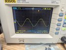
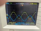
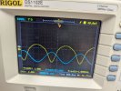
Ok after some head scratching I found my mistake. I am attaching the scope pictures of the latest build.
Scope Pictures
First - right before clipping
Second - Clipping
Third - Right before clipping. Yellow output and blue input
Fourth - Clipping. Yellow Output and Blue Input
6an8 pin 1 and 3 have 39k 1 watt. Pin 3 has the 39k then a 5k trimmer then ground. I do have a 10k I could change it to.
6v6
Pin 1 - 0 0
Pin 2 - 21 21
Pin 3 - 324 328
Pin 4 - 331 331
Pin 5 - 0 0
Pin 6 - 0 0
Pin 7 - 21 21
Pin 8 - 21 21
6AN8
Pin 1 - 166
Pin 2 - 58
Pin 3 - 64
Pin 4 - 21
Pin 5 - 21
Pin 6 - 58
Pin 7 - 18
Pin 8 - 0
Pin 9 - 0
40uF - 333
30uF - 333
10uF - 230 - I dropped this to a 47k and I still get 230vdc after it settles. Guess I need to keep going lower. I'm sure there is some math that gets me the right value.
More questions about this choke. The original 169BB schematic shows the choke and/or a 470/2w resistor. The choke only has a resistance of 56 ohms. I'm thinking there should be more resistance. Should I have both?
Scope Pictures
First - right before clipping
Second - Clipping
Third - Right before clipping. Yellow output and blue input
Fourth - Clipping. Yellow Output and Blue Input
6an8 pin 1 and 3 have 39k 1 watt. Pin 3 has the 39k then a 5k trimmer then ground. I do have a 10k I could change it to.
6v6
Pin 1 - 0 0
Pin 2 - 21 21
Pin 3 - 324 328
Pin 4 - 331 331
Pin 5 - 0 0
Pin 6 - 0 0
Pin 7 - 21 21
Pin 8 - 21 21
6AN8
Pin 1 - 166
Pin 2 - 58
Pin 3 - 64
Pin 4 - 21
Pin 5 - 21
Pin 6 - 58
Pin 7 - 18
Pin 8 - 0
Pin 9 - 0
40uF - 333
30uF - 333
10uF - 230 - I dropped this to a 47k and I still get 230vdc after it settles. Guess I need to keep going lower. I'm sure there is some math that gets me the right value.
More questions about this choke. The original 169BB schematic shows the choke and/or a 470/2w resistor. The choke only has a resistance of 56 ohms. I'm thinking there should be more resistance. Should I have both?
Attachments


Last edited:
Generally to get open loop gain you would use a small output- around 2V works well.
But, using the third picture, Vout = 9.68 and Vin = 7.18mV
AV = 1,348X = 62.6dB, pretty ridiculously high. And this is with 8 ohm output into rated 8 ohm load? Huh.
6V6 plates are lower than the screens, still have 0V dropped through the choke. (shorted maybe?) 6V6 biasing is unchanged, looks great.
6AN8
Pin 1 - 166
Pin 2 - 58 (pentode plate, cathodyne input, looks better than before)
Pin 3 - 64 (cathodyne cathode, 64V looks great.)
Pin 4 - 21 (elevated filament as expected)
Pin 5 - 21 " "
Pin 6 - 58 (pentode plate, cathodyne input.)
Pin 7 - 18
Pin 8 - 0
Pin 9 - 0 (There is our low resolution incorrect voltage reading again. Need to buy you an auto-ranging voltmeter.)
The cathodyne is passing 64V/(39K + 5K?) ~ about 1.5mA. The lower output is DC 64V at idle, the upper output is DC 166V at idle, meaning you are dropping 64V across the bottom resistor, 64V across the top resistor, and 102V across the tube. Looking pretty good there.
(continued below the pictures)
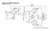
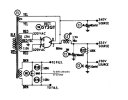
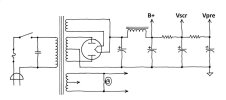
I'll be honest, I don't really like how this power supply is designed. In this factory design (modified by Jason?) the choke is the only drop between B+ and the screen supply. The choke likely has a lower DCR than the CT to plate half primary winding of the output transformer. This means that the screens will track higher than the plate voltage, especially at high power levels which is generally a bad thing. This could be fixed with a dropping resistor, but I still think this supply can be a bit better.
Generally, a push-pull amp will have the filtering scheme shown on the right. B+ (OPT supply) is usually taken from the second cap, which minimizes ripple yet still provides good stiff regulation because of the low DCR of the choke. The dropping resistor between the 2nd and 3rd cap for the screen supply is usually sized so that the screen supply tracks pretty well (or just below) the output tube plate voltage when under load at near maximum output power. Usually this is less than 1K. The second dropping resistor for the Vpre supply would then be larger, and fairly arbitrary to achieve whatever preamp supply voltage you like. It's not a really bad thing to take B+ from the first cap, but from the second is so much cleaner.
But, using the third picture, Vout = 9.68 and Vin = 7.18mV
AV = 1,348X = 62.6dB, pretty ridiculously high. And this is with 8 ohm output into rated 8 ohm load? Huh.
Generally the idea is to be able to set upper and lower resistors equal to each other (or slightly above or below). You might throw a 1/4 watt 470K in parallel with the lower fixed resistor to drop it to around 36K.6an8 pin 1 and 3 have 39k 1 watt. Pin 3 has the 39k then a 5k trimmer then ground. I do have a 10k I could change it to.
6V6 plates are lower than the screens, still have 0V dropped through the choke. (shorted maybe?) 6V6 biasing is unchanged, looks great.
6AN8
Pin 1 - 166
Pin 2 - 58 (pentode plate, cathodyne input, looks better than before)
Pin 3 - 64 (cathodyne cathode, 64V looks great.)
Pin 4 - 21 (elevated filament as expected)
Pin 5 - 21 " "
Pin 6 - 58 (pentode plate, cathodyne input.)
Pin 7 - 18
Pin 8 - 0
Pin 9 - 0 (There is our low resolution incorrect voltage reading again. Need to buy you an auto-ranging voltmeter.)
The cathodyne is passing 64V/(39K + 5K?) ~ about 1.5mA. The lower output is DC 64V at idle, the upper output is DC 166V at idle, meaning you are dropping 64V across the bottom resistor, 64V across the top resistor, and 102V across the tube. Looking pretty good there.
Well, with (333V-230V)/47K you have about about 2.2mA flowing. It's not a straightforward calculation because as you decrease the resistor the current increases, partially defeating your increase. I would try something in the 15K range and see how that looks.10uF - 230 - I dropped this to a 47k and I still get 230vdc after it settles. Guess I need to keep going lower. I'm sure there is some math that gets me the right value.
I would not. Dropping resistor was used to provide cheap resistive isolation (forming an RC filter stage) to decrease ripple. Chokes are more expensive, and the inductance provides much better filtering. You have on the order of 78mA + 3mA = 81mA at least flowing through that choke, and with a 56 ohm DC resistance you should be seeing on the order of 4-5V drop across the choke. If you don't, it's either mis-wired, or shorted.More questions about this choke. The original 169BB schematic shows the choke and/or a 470/2w resistor. The choke only has a resistance of 56 ohms. I'm thinking there should be more resistance. Should I have both?
(continued below the pictures)
I'll be honest, I don't really like how this power supply is designed. In this factory design (modified by Jason?) the choke is the only drop between B+ and the screen supply. The choke likely has a lower DCR than the CT to plate half primary winding of the output transformer. This means that the screens will track higher than the plate voltage, especially at high power levels which is generally a bad thing. This could be fixed with a dropping resistor, but I still think this supply can be a bit better.
Generally, a push-pull amp will have the filtering scheme shown on the right. B+ (OPT supply) is usually taken from the second cap, which minimizes ripple yet still provides good stiff regulation because of the low DCR of the choke. The dropping resistor between the 2nd and 3rd cap for the screen supply is usually sized so that the screen supply tracks pretty well (or just below) the output tube plate voltage when under load at near maximum output power. Usually this is less than 1K. The second dropping resistor for the Vpre supply would then be larger, and fairly arbitrary to achieve whatever preamp supply voltage you like. It's not a really bad thing to take B+ from the first cap, but from the second is so much cleaner.

You have on the order of 78mA + 3mA = 81mA at least flowing through that choke,
Consider only the screens and the 6AN8 pull any power through the choke in it's stock configuration. The 6AN8 I was showing around 1mA on my power supply, and idle screen current on a 6V6 at these sort of voltages is probably around 4mA. Full scream is probably 13-14mA, so worst-case, approx 15mA.
If its been re-configured so the plate supply comes through it, it will be considerably higher but I also suspect that stock choke isn't going to handle that much extra current.
Yep, DURP! My bad- you're right. That's why there is no drop duh. Only tiny screen and pre current flowing through it. Sheesh. Can't believe I missed that.
Its a Hammond 156R choke, good for 200mA. Snuck it in a picture here.
Another reason to reconstruct the power supply as shown in my generic template on the right- the 5Y3 is only supposed to have 20uF attached directly to it's cathode- so the caps moving from left to right would be 22uF, 47uF, 33uF and 10uF. Choke is 156R, screen dropping resistor in the ballpark of 470 ohms, and the pre-amp dropping resistor in the 10K-15K range.
Its a Hammond 156R choke, good for 200mA. Snuck it in a picture here.
Another reason to reconstruct the power supply as shown in my generic template on the right- the 5Y3 is only supposed to have 20uF attached directly to it's cathode- so the caps moving from left to right would be 22uF, 47uF, 33uF and 10uF. Choke is 156R, screen dropping resistor in the ballpark of 470 ohms, and the pre-amp dropping resistor in the 10K-15K range.
I have a good Fluke around here somewhere. I'll find it this morning.Need to buy you an auto-ranging voltmeter
This is the factory design. The jason mod is removing the resistor and using the hammond choke.In this factory design (modified by Jason?)
I'll double check but I'm pretty sure I do not have caps with high enough voltage. I have a 100, 40, 30, and 10 at 500v. I'll see what I have and order what I don't.Another reason to reconstruct the power supply as shown in my generic template
Power Supply rewired. I found a 22uf 450v in my stash.
Left to right.
22uF - 332Vdc
40uF - 329 - b+
30 uF - 325 - vscr
10uF - 297 - vpre
6V6
1- 0 0
2- 20.5 20.5
3- 324 320
4- 325 325
5- 0 0
6- 0 0
7- 20.7 20.7
8- 20.7 20.7
6AN8
1- 205
2- 82
3- 91
4- 20.6
5- 20.6
6- 82
7- 25
8- 0
9- .98
Left to right.
22uF - 332Vdc
40uF - 329 - b+
30 uF - 325 - vscr
10uF - 297 - vpre
6V6
1- 0 0
2- 20.5 20.5
3- 324 320
4- 325 325
5- 0 0
6- 0 0
7- 20.7 20.7
8- 20.7 20.7
6AN8
1- 205
2- 82
3- 91
4- 20.6
5- 20.6
6- 82
7- 25
8- 0
9- .98
Attachments

Last edited:
that looks good, the voltage split across the inverter is where it belongs for best voltage swing. In a perfect world you want basically between 1/3 and 1/2 the supply voltage from plate to cathode. Supply 297, you're dropping 114v which is right in that zone. The closer to half the supply voltage you get the more voltage swing it can make but this should have ample headroom. Also being direct coupled every single 6an8 will split that a little different so no reason to go nuts about it.
Power supply voltages look awesome! Tell me what dropping resistors and capacitor values you used and I can draw up the power supply correctly and add it to the channel schematic. Also- what were the final values on the cathodyne load resistors?
6V6's continue to look awesome.
6AN8
1- 205 (cathodyne plate output
2- 82 (cathodyne grid
3- 91 (cathodyne cathode
4- 20.6 (elevated fil)
5- 20.6 " "
6- 82 (pentode plate )
7- 25 (pentode screen)
8- 0
9- .98 (pentode cathode)
The pentode plate being at 205V means the pentode plate current is (297-205)/470K ~ 0.2mA, screen current is (297-25)/2.2M ~ .124mA, and cathode current is 0.98/1720 ~ .57mA which does not add up, but I did not really expect it to. (So much opportunity for measurement error, especially on the screen.) I am really liking the pentode cathode voltage of about 1V- much better than before, that will give you decent swing room, but we probably want final closed loop sensitivity to be a bit on the high side, so final listening ranges are well within the swing room provided the grid.
As @gadget73 just indicated, you have 91V across the bottom leg, (297-205)=92V across the top leg, and 114V across the tube. Basically perfect.
The scope picture looks beautiful. Vout = 2.06V, Vin = 9.42mV
AV = 219X
AV(dB) = 47dB
Not bad. Since we want higher sensitivity, maybe as high as 20X (~27dB) we could try to use 20dB of global negative feedback and see how it works out, but I'm not sure if we want to do that. @gadget73, I think we need to drop the open loop gain a bit?
I think maybe reduce the 470K pentode plate resistor some?
6V6's continue to look awesome.
6AN8
1- 205 (cathodyne plate output
2- 82 (cathodyne grid
3- 91 (cathodyne cathode
4- 20.6 (elevated fil)
5- 20.6 " "
6- 82 (pentode plate )
7- 25 (pentode screen)
8- 0
9- .98 (pentode cathode)
The pentode plate being at 205V means the pentode plate current is (297-205)/470K ~ 0.2mA, screen current is (297-25)/2.2M ~ .124mA, and cathode current is 0.98/1720 ~ .57mA which does not add up, but I did not really expect it to. (So much opportunity for measurement error, especially on the screen.) I am really liking the pentode cathode voltage of about 1V- much better than before, that will give you decent swing room, but we probably want final closed loop sensitivity to be a bit on the high side, so final listening ranges are well within the swing room provided the grid.
As @gadget73 just indicated, you have 91V across the bottom leg, (297-205)=92V across the top leg, and 114V across the tube. Basically perfect.
The scope picture looks beautiful. Vout = 2.06V, Vin = 9.42mV
AV = 219X
AV(dB) = 47dB
Not bad. Since we want higher sensitivity, maybe as high as 20X (~27dB) we could try to use 20dB of global negative feedback and see how it works out, but I'm not sure if we want to do that. @gadget73, I think we need to drop the open loop gain a bit?
I think maybe reduce the 470K pentode plate resistor some?
I am thinking we can decrease the plate resistor, which has the benefit of increasing the pentode plate voltage, also increases the current some, which will also lift that cathode up even further. Gain could also be decreased by increasing the 220 ohm "AC" cathode resistor, which to a first order also raises the cathode, but not as much as you would think because it also decreases the current and will drop the plate voltage further.
So, why not try a pentode plate resistor of say 330K or 220K and see where we land? All you really need to snag then is the pentode plate and cathode voltage, and redo the open loop gain.
So, why not try a pentode plate resistor of say 330K or 220K and see where we land? All you really need to snag then is the pentode plate and cathode voltage, and redo the open loop gain.
Lets start with the power supply. The resistor between B+ and Vscr is 470. The resistor between Vscr and Vpre is 10k.
I did not decrease the plate resistor yet. I have 330k and 220k sitting on the bench ready to solder one in.
There is no feedback from the output to pin 9 yet. Just wanted to make that clear as we look at voltages.
I have some time before dinner so I'll go solder a 220k in place of the 470k on the plate. I'll grab another 2vrms picture, the two voltages and return.
I did not decrease the plate resistor yet. I have 330k and 220k sitting on the bench ready to solder one in.
I did not do this yet. I have the trim pot (5k) set to zero resistance. The resistor through the trim pot (at 0) measures 38.8k ohms. Are these the cathodyne load resistors? 6AN8 pin 1 and pin 3. They are 39k 1 watt that measure 38.8k on my fluke.You might throw a 1/4 watt 470K in parallel with the lower fixed resistor to drop it to around 36K.
There is no feedback from the output to pin 9 yet. Just wanted to make that clear as we look at voltages.
I have some time before dinner so I'll go solder a 220k in place of the 470k on the plate. I'll grab another 2vrms picture, the two voltages and return.
6AN8
Pin 3 - 155
Pin 6 - 133
Pin 9 - .98
I changed out the 470k that goes from the 230v to Pin 6 on the 6AN8 to a 220k. Things look ugly now. I also have to crank the signal generator higher to get output. Looks like time to try the 330k?
Pin 3 - 155
Pin 6 - 133
Pin 9 - .98
I changed out the 470k that goes from the 230v to Pin 6 on the 6AN8 to a 220k. Things look ugly now. I also have to crank the signal generator higher to get output. Looks like time to try the 330k?
Attachments

Pin 3 is the cathodyne cathode- no idea why it would now be so high, and it's 22V! higher than the pentode plate? Something is wonky here.6AN8
Pin 3 - 155
Pin 6 - 133
Pin 9 - .98
Yes, I would try 330K, and double check everything.
Here is the latest version of the schematic. Continue to indicate changes/corrections. What are the colors of the OPT leads, and do you want the other taps shown? (I assume you are only using 8 ohm)
== updated schematic below ==
Last edited:
OPT wires are white/blue, blue are input. Green/white, green are UL taps. Red is b+. Out taps are black is ground. orange is 8 ohm. brown is 4 ohm.
The 10k wasnt enough to reach 300v after it settled. I switched it out for a 5.6k Now I'm reading 300v at the 10uF.
330k Installed. Still looks bad. Back to the 470k? I'll switch it back after dinner.
The 10k wasnt enough to reach 300v after it settled. I switched it out for a 5.6k Now I'm reading 300v at the 10uF.
330k Installed. Still looks bad. Back to the 470k? I'll switch it back after dinner.
Attachments
Ok, so which color do you have connected to which 6V6? (Polarity?)
Yeah- i would switch back to 470K- that looked beautiful. I still think something wonky is going on though- it should not look that way with either 330K or 220K. And the input amplitude should not be so very different. Check your scope probe 1X and 10X settings- 1X is usually used for 40V and below, so I'm almost always on 1X. 10X has a 10:1 voltage divider, which reduces the input capacitance, increases the input resistance, and makes the probe safe on high voltage generally up to 400V, so I only use 10X on plate signals. You had like a 10X change in input amplitude, so I am suspicious.
I frankly don't do this work with O-scope running dual channel. Ground out at the load will be different, and bouncing compared to input ground- I don't connect them together through the probe grounds. I always work single channel, load picture is with load ground, input picture is with input ground. You got good results with the 470K, so I don't know what has changed.
Yeah- i would switch back to 470K- that looked beautiful. I still think something wonky is going on though- it should not look that way with either 330K or 220K. And the input amplitude should not be so very different. Check your scope probe 1X and 10X settings- 1X is usually used for 40V and below, so I'm almost always on 1X. 10X has a 10:1 voltage divider, which reduces the input capacitance, increases the input resistance, and makes the probe safe on high voltage generally up to 400V, so I only use 10X on plate signals. You had like a 10X change in input amplitude, so I am suspicious.
I frankly don't do this work with O-scope running dual channel. Ground out at the load will be different, and bouncing compared to input ground- I don't connect them together through the probe grounds. I always work single channel, load picture is with load ground, input picture is with input ground. You got good results with the 470K, so I don't know what has changed.
All I did was switch back to the 470k and the picture is attached.
2vrms with 6.8mV input. I checked them separately instead of dual channel as suggest. I have been considering getting a second scope. Would it be bad to do the same input and output if i had a scope for each?
OK OPT polarity. Looking at the schematic the top 6V6 is the blue wire. The bottom is blue/white.
2vrms with 6.8mV input. I checked them separately instead of dual channel as suggest. I have been considering getting a second scope. Would it be bad to do the same input and output if i had a scope for each?
OK OPT polarity. Looking at the schematic the top 6V6 is the blue wire. The bottom is blue/white.
Attachments

Something is really wonky. Check your resistor values and scope settings. 330K = 2V with 32mV input, 470K = 2V with 2mV (or 6.8mV?) input? I don't buy it.
I would not use two scopes at the same time.
I use BNC to RCA adapters, and all of my signal generator and scope cabling is cheap RCA cables and a couple of RCA female to male splitters. Works great, very fast plug and play. I don't drag out a dorky probe unless I need to grab something deep in the chassis.
I would not use two scopes at the same time.
I use BNC to RCA adapters, and all of my signal generator and scope cabling is cheap RCA cables and a couple of RCA female to male splitters. Works great, very fast plug and play. I don't drag out a dorky probe unless I need to grab something deep in the chassis.