

You are using an out of date browser. It may not display this or other websites correctly.
You should upgrade or use an alternative browser.
You should upgrade or use an alternative browser.
Magnavox 169 BB Output Transformers
- Thread starter Rudiger
- Start date

One thing I just noticed- With the use of a 4.7 Meg grid return resistor they are getting some "grid biasing" going on- this enables the grid to drop to -0.2V from electron leakage onto the grid, in addition to the .8V they claim on the cathode, giving the grid the same swing room as if the cathode were closer 1V. (if true.) When I changed the grid return from 4.7M to 470K due to noise concerns, this effect went away and the grid is now effectively at ground. I still stand by that change- as a stand alone amp you may be in more noise prone situations than the original console/record player.
After we start getting a good idea of the performance of the amp, there are some more possible tweaks here if we need- We could increase the 1500 ohm resistor to more like 2.2K or 2.5K, and that will drop the bias current a bit and raise the plate voltage some. If it were mine I might put a pot there and play with it. Generally you want to be able to drive an amp to maximum power with an input signal that is smaller than or equal to 1V RMS- that's a 1.4V peak, so ideally I like to try to get the cathode up to 1.4V (with a grid at ground) but it's not always possible.
Let's also see what voltage you actually measure on those two cathodes.

After we start getting a good idea of the performance of the amp, there are some more possible tweaks here if we need- We could increase the 1500 ohm resistor to more like 2.2K or 2.5K, and that will drop the bias current a bit and raise the plate voltage some. If it were mine I might put a pot there and play with it. Generally you want to be able to drive an amp to maximum power with an input signal that is smaller than or equal to 1V RMS- that's a 1.4V peak, so ideally I like to try to get the cathode up to 1.4V (with a grid at ground) but it's not always possible.
Let's also see what voltage you actually measure on those two cathodes.
Attachments

6AN8
Pin 3 is 1.01vdc
Pin 9 - .8vdc
Pictures of scope are attached. It is not clipping symmetrically. Looks like 14mV in is getting 2.02v out. Bottom half clipping starts around 8.5v.
I have not mentioned quality of these tubes yet. I assume that makes a difference. The tubes currently installed appear to be original. They are marked magnavox on the base of the 6v6. The 5y3 is a sylvania. I was told when I purchased this that they tested good on their tube tester. I have NOS 6AN8, new Sovtek 5y3 and new tung sol 6v6 on the way.
Pin 3 is 1.01vdc
Pin 9 - .8vdc
Pictures of scope are attached. It is not clipping symmetrically. Looks like 14mV in is getting 2.02v out. Bottom half clipping starts around 8.5v.
I have not mentioned quality of these tubes yet. I assume that makes a difference. The tubes currently installed appear to be original. They are marked magnavox on the base of the 6v6. The 5y3 is a sylvania. I was told when I purchased this that they tested good on their tube tester. I have NOS 6AN8, new Sovtek 5y3 and new tung sol 6v6 on the way.
Attachments


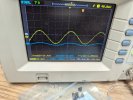
Ok. What is the last picture? (both ~14/15mVrms?)
Yes, tube strength is important. The high voltages look great, so I think the 5Y3 is working fine. When it comes to a push-pull set of outputs, we generally look at the plate voltages, and they are fairly balanced (325 and 329) but given the only series resistance is the OPT primary that may not tell the clear story. The combined bias currents of 78mA for the two tubes is pretty healthy, so it does not seem there is a problem with either one of those, but swapping the two output tubes and seeing no change will help you gain confidence there. If you want to gauge how well the tubes are actually matched, you can put a 10 ohm or lower resistor in series between each cathode and the shared 270 ohm cathode resistor to measure how much actual cathode current is being contributed from each. The 6AN8A also seems to be performing about as expected, so to a first order I don't suspect a tube issue, but a biasing issue in either the pentode, triode, or both. It will be interesting if you swap in the NOS 6AN8 and see if there is a difference here.
Pin 3 (triode cathode = 1.01V) is about what is expected (~1.1).
Pin 9 (pentode cathode = .8V) is a bit low, but works OK for now.
AV = 2.02/.0139 = 145.3 X (pretty high!)
AV(dB) = 20*LOG(145.3) = 43dB
That is a HUGE amount of gain- very sensitive. Once you have open loop gain measured in dB, you can then make a decision to trade off how much sensitivity you want (closed loop gain) versus amount of negative feedback. The final closed loop gain in dB is the open loop gain minus the amount of negative feedback. Say you wanted an amplifier that puts out maximum power with 1V RMS input. A 6V6 push-pull is going to be about a 10W maximum output into rated load. Maybe a bit more here because of your higher voltages, but let's say 10W. I assume you are using an 8 ohm load. 10W into 8 ohms is ~8.9V RMS. 8.9V with 1V input is a gain of 8.9X, but there is some squashing that happens as you get close to clipping, so it needs to be a bit higher, so let's say it's 10X. That's 20dB of closed loop gain. With 43dB of open loop gain to start with, you could apply theoretically 23dB of global negative feedback. That's really, way too high. The amplifier will likely be unstable if you try to use that much. Generally, 20dB of negative feedback is considered a healthy, maximum amount if you have really good transformers. But usually, with cheaper transformers you can't keep the amp stable with more than about 11 to 18dB of feedback. Rather than try to see if we can use that much feedback, I think it's wise to drop the open loop gain back a bit, to maybe 38dB (80X) or less.
Since you seem pretty comfortable with the scope, it would be interesting to use 10X setting on the probes, and see what the grid drive signals look like at the input (plate) side of each coupling cap as you approach clipping. That will tell us how symmetrical they are and which one is crapping out at higher amplitude. Given the previously identified super low triode plate voltage I bet that is the problem- too little swing room. Given the super high gain, we should be able to drop the two 470K plate resistors down some (I'd try 330K, 220K, etc) and see how the voltages, max power waveform, and open loop gain changes. If the lower grid signal is pretty small compared to the upper grid signal, we can up the gain on the lower inverter triode as well- you can actually just jumper between the pin 3 cathode of the 6AN8 to the positive side of the 100uF bypass cap that is right there. That is basically what was done on the Magnavox 9300, and should work great.
Yes, tube strength is important. The high voltages look great, so I think the 5Y3 is working fine. When it comes to a push-pull set of outputs, we generally look at the plate voltages, and they are fairly balanced (325 and 329) but given the only series resistance is the OPT primary that may not tell the clear story. The combined bias currents of 78mA for the two tubes is pretty healthy, so it does not seem there is a problem with either one of those, but swapping the two output tubes and seeing no change will help you gain confidence there. If you want to gauge how well the tubes are actually matched, you can put a 10 ohm or lower resistor in series between each cathode and the shared 270 ohm cathode resistor to measure how much actual cathode current is being contributed from each. The 6AN8A also seems to be performing about as expected, so to a first order I don't suspect a tube issue, but a biasing issue in either the pentode, triode, or both. It will be interesting if you swap in the NOS 6AN8 and see if there is a difference here.
Pin 3 (triode cathode = 1.01V) is about what is expected (~1.1).
Pin 9 (pentode cathode = .8V) is a bit low, but works OK for now.
AV = 2.02/.0139 = 145.3 X (pretty high!)
AV(dB) = 20*LOG(145.3) = 43dB
That is a HUGE amount of gain- very sensitive. Once you have open loop gain measured in dB, you can then make a decision to trade off how much sensitivity you want (closed loop gain) versus amount of negative feedback. The final closed loop gain in dB is the open loop gain minus the amount of negative feedback. Say you wanted an amplifier that puts out maximum power with 1V RMS input. A 6V6 push-pull is going to be about a 10W maximum output into rated load. Maybe a bit more here because of your higher voltages, but let's say 10W. I assume you are using an 8 ohm load. 10W into 8 ohms is ~8.9V RMS. 8.9V with 1V input is a gain of 8.9X, but there is some squashing that happens as you get close to clipping, so it needs to be a bit higher, so let's say it's 10X. That's 20dB of closed loop gain. With 43dB of open loop gain to start with, you could apply theoretically 23dB of global negative feedback. That's really, way too high. The amplifier will likely be unstable if you try to use that much. Generally, 20dB of negative feedback is considered a healthy, maximum amount if you have really good transformers. But usually, with cheaper transformers you can't keep the amp stable with more than about 11 to 18dB of feedback. Rather than try to see if we can use that much feedback, I think it's wise to drop the open loop gain back a bit, to maybe 38dB (80X) or less.
Since you seem pretty comfortable with the scope, it would be interesting to use 10X setting on the probes, and see what the grid drive signals look like at the input (plate) side of each coupling cap as you approach clipping. That will tell us how symmetrical they are and which one is crapping out at higher amplitude. Given the previously identified super low triode plate voltage I bet that is the problem- too little swing room. Given the super high gain, we should be able to drop the two 470K plate resistors down some (I'd try 330K, 220K, etc) and see how the voltages, max power waveform, and open loop gain changes. If the lower grid signal is pretty small compared to the upper grid signal, we can up the gain on the lower inverter triode as well- you can actually just jumper between the pin 3 cathode of the 6AN8 to the positive side of the 100uF bypass cap that is right there. That is basically what was done on the Magnavox 9300, and should work great.
I have parallel RCA's coming off my signal generator. The third picture is yellow amplifier output and blue is the input. I couldn't believe it was so low input that the last picture is me plugging both signal generator outputs into the scope to make sure they read the same.
I am using 8ohm load and have the 8 ohm OPT tap connected.
To be clear you want a to see a waveform from the 6an8 pin 1 and pin 6. The yellow waveform is pin 6 and blue is pin 1 on 6an8. First two are probes at 1x and second two are probes at 10x.
I am using 8ohm load and have the 8 ohm OPT tap connected.
To be clear you want a to see a waveform from the 6an8 pin 1 and pin 6. The yellow waveform is pin 6 and blue is pin 1 on 6an8. First two are probes at 1x and second two are probes at 10x.
Attachments

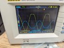
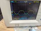


with no feedback loop complete, it will have a ton of gain
the asymmetrical clipping even at lower levels tells me something isn't as it should be. Looks like its clipping on the pentode side so that needs to be fixed first, then the significant imbalance.
If I've got some time this weekend I may knock together a copy of this driver circuit and see if something can be done with it. I suspect its going to involve running both sections at a little higher current to put them into a happier operating zone. That will mean changing that 100K in the power supply, but thats trivial.
the asymmetrical clipping even at lower levels tells me something isn't as it should be. Looks like its clipping on the pentode side so that needs to be fixed first, then the significant imbalance.
If I've got some time this weekend I may knock together a copy of this driver circuit and see if something can be done with it. I suspect its going to involve running both sections at a little higher current to put them into a happier operating zone. That will mean changing that 100K in the power supply, but thats trivial.
You are probably going to kill me for suggesting this- What if we just bagged this wicked imbalanced scenario, (high output impedance pentode trying to match a very low output impedance triode) and convert instead to pentode driving cathodyne inverter using that wonderful medium-mu triode we have? Perhaps even direct coupled? I think it would give WAY better performance. What do you think?
=I'm working up a proposed schematic on that, will be reviewable later today if you are interested.=
=I'm working up a proposed schematic on that, will be reviewable later today if you are interested.=
Last edited:
direct coupled split load is easy and works well, specifically for it being done with a 6AN8, the Dyna Mark III is an example. Higher voltages, you won't need those exact values but the idea is there. Less phase shift points so it lends itself to better LF stability.
for a pentode / triode floating paraphase though, HH Scott used that in some amps. The 299 and 299B did it that way using a 6BL8.
299A

299B

for a pentode / triode floating paraphase though, HH Scott used that in some amps. The 299 and 299B did it that way using a 6BL8.
299A
299B
Here is my first pass schematic to consider. If we work out the voltages correctly, C? coupling cap may not be needed- (direct coupled). We still need to straighten out the gain and swing of the pentode, and the bias/plate/cathode resistors of the cathodyne, but I think this will perform much better.
Thoughts? @Rudiger?
=Schematic removed, updated below. =
Thoughts? @Rudiger?
=Schematic removed, updated below. =
Last edited:
I'm all for the best performance we can get. At this point my only catch is I already ordered the tubes so we can't be switching to different tubes.
So when you figure out what values to start with ill rewire and get the voltages you need to get moving forward.
So when you figure out what values to start with ill rewire and get the voltages you need to get moving forward.
Here's my take on the values. The plate of the pentode is assumed to eventually be around 70V. That will position the cathode voltage of the cathodyne nicely, and with matching 33K plate and cathode resistors you will put the plate around (230 - 70) or 160V, so you will have beautiful large swing room.
You may have to play with decreasing the 100k dropping resistor to maintain the 230V on the front end- the cathodyne will pull a little over 2mA so that supply will drop. I consider 230V to be the minimum, but it's what the pentode setup was designed for so to a first order keep it around that.
I do want to apologize for leading you on a snipe hunt with the floating paraphase. I figured since others have done this with a pentode/triode combination, and we were just converting from classical to floating paraphase, things would go better. I should have realized that the 6AN8 triode was such a low mu tube- when the floating paraphase is most successful, it's using a dual triode like the 12AX7, where both sections are nominally identical. I consider the cathodyne phase inverter to be quite excellent, on par with the performance we wanted with the floating paraphase, so I think this is a really superior way to go and you will be VERY happy with the performance.
== Schematic removed and updated version appears below ==
Some additional changes I might suggest- The forward open loop gain of this circuit should be the same as it was before - 43dB, which we need to decrease some. I would consider changing the 1500 ohm bypassed cathode resistor to more like 2.2K, and the plate resistor of 470K can be dropped to either 330K or even 220K. We might need to iterate a bit- we want both gain in the 35-38dB range, and the pentode plate voltage to be good for the cathodyne positioning, around 70V or so.
If you want the ability to minimize distortion, one really nice hack is to change the bottom 33K resistor to a fixed resistor in series with a trimmer pot, which enables you to fine tune the amplitude of the inverted grid signal to balance out other imbalances in the system, such as output tube mismatch and output transformer asymmetry. This would look like a 30K fixed resistor with a 5K linear trimmer, or something along those lines.
You may have to play with decreasing the 100k dropping resistor to maintain the 230V on the front end- the cathodyne will pull a little over 2mA so that supply will drop. I consider 230V to be the minimum, but it's what the pentode setup was designed for so to a first order keep it around that.
I do want to apologize for leading you on a snipe hunt with the floating paraphase. I figured since others have done this with a pentode/triode combination, and we were just converting from classical to floating paraphase, things would go better. I should have realized that the 6AN8 triode was such a low mu tube- when the floating paraphase is most successful, it's using a dual triode like the 12AX7, where both sections are nominally identical. I consider the cathodyne phase inverter to be quite excellent, on par with the performance we wanted with the floating paraphase, so I think this is a really superior way to go and you will be VERY happy with the performance.
== Schematic removed and updated version appears below ==
Some additional changes I might suggest- The forward open loop gain of this circuit should be the same as it was before - 43dB, which we need to decrease some. I would consider changing the 1500 ohm bypassed cathode resistor to more like 2.2K, and the plate resistor of 470K can be dropped to either 330K or even 220K. We might need to iterate a bit- we want both gain in the 35-38dB range, and the pentode plate voltage to be good for the cathodyne positioning, around 70V or so.
If you want the ability to minimize distortion, one really nice hack is to change the bottom 33K resistor to a fixed resistor in series with a trimmer pot, which enables you to fine tune the amplitude of the inverted grid signal to balance out other imbalances in the system, such as output tube mismatch and output transformer asymmetry. This would look like a 30K fixed resistor with a 5K linear trimmer, or something along those lines.
Last edited:
some testing with the floating paraphase design. Can confirm a roughly 2:1 imbalance which isn't going to be happy. I was able to get good balance out of it with clean 40v p-p of output though. It wants more voltage to get that much output swing, so the 100K in the power supply needs to change. At 300v this draws a little under 1mA so changing R22 to something in the 33K range I think will serve. That voltage isn't too critical, its fine if it ends up a little higher.
forgot to draw it in but both of those cathode caps are the same value. The originally specified 100uF 25v is fine, I happened to have 47uF on hand. The screen cap value is also not critical, I used what I had. I did go with a film cap though, with a 2.2M supply resistor leakage is an important consideration.
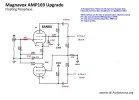
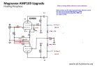
forgot to draw it in but both of those cathode caps are the same value. The originally specified 100uF 25v is fine, I happened to have 47uF on hand. The screen cap value is also not critical, I used what I had. I did go with a film cap though, with a 2.2M supply resistor leakage is an important consideration.
And the other. Quite frankly this performs much better. Current draw is slightly higher, approx 1mA total so the 100K in the power supply may need adjustment to get the 230v. That voltage isn't super critical, and honestly the output cleans up some if its higher. I'd be fine with this at 300v B+. At a 300v supply it will do almost 90v p-p.
At 230v of B+ and output at 40v p-p, I get approx 1v p-p of imbalance, which could probably be made better with hand-selected 33K resistors. I grabbed the first two that fell out of the bag of very cheap 5% parts and stuck them in, but the closer the match, the better the balance will be.
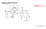
At 230v of B+ and output at 40v p-p, I get approx 1v p-p of imbalance, which could probably be made better with hand-selected 33K resistors. I grabbed the first two that fell out of the bag of very cheap 5% parts and stuck them in, but the closer the match, the better the balance will be.
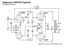
Appears @Rudiger, you have two great choices! I made the same change to the pentode screen bypass- 1uF film
I'm keeping the pre-amp supply at 230V for now- if we adjust that up do we want to increase the cathodyne load resistors to more like 47K? The plate of the pentode is still pretty low (~50ish volts) but that too will be better with the higher voltage- if we increase that to 300V we might need to drop the pentode plate resistor too?
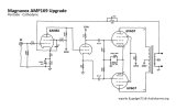
I'm keeping the pre-amp supply at 230V for now- if we adjust that up do we want to increase the cathodyne load resistors to more like 47K? The plate of the pentode is still pretty low (~50ish volts) but that too will be better with the higher voltage- if we increase that to 300V we might need to drop the pentode plate resistor too?
Last edited:
Oh I got parts. So the consensus is the Cathodyne setup then. That looks like an easier change.between me you and the tree, if you've got the parts to make this split load, I'd do that. Its a better setup.
While you are building it I would reduce that 100K dropping resistor in the power supply to see if you can get the pre-amp supply closer to 300V as @gadget73 suggested for better swing-room and cleaner output. I'm interested to see where the pentode and cathodyne voltages land, and we can tweak from there. You probably want to use half watt or even 1 watt resistors on the 33K, and try to match them.