• Please note that Audiokarma will be offline briefly for updates early on Monday morning, September 28th.

Magnavox 8802 visits Kegger

Paint is done....

35e9513d.jpg


Other than wood, this is it. I'm getting a couple of other maggotboxes back from a woodworker friend of mine next Monday. We'll see what they look like. Meanwhile as soon as this dries, I'm gonna fire up the ol soldering iron.....:thmbsp:
 
Very nice.. ;)

------

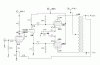
I recently made the schematics a little easier to read/understand, here's a copy.
.
 

Attachments

  • 6K6_275V_PP_6BL8_SUPPLY_FNL_done.GIF
    6K6_275V_PP_6BL8_SUPPLY_FNL_done.GIF
    5.6 KB · Views: 171
  • 6K6_275V_PP_6GH8_6BL8_FNL_done.GIF
    6K6_275V_PP_6GH8_6BL8_FNL_done.GIF
    10.9 KB · Views: 211
Those 50 ohm resistors in the PS are a perfect place to put a couple of the 1 Henry 56 ohm chokes you find on that auction site.

Jim, AB0EZ
 
I would wholeheartedly agree.. ;)

(even though if you simm the supply with those caps it's pretty clean for an inexpensive supply).. :thmbsp:
 
There isn't a lot of room in those chassis, I got creative for Andy to get a decent supply in there though.
 
That's the truth. I had one a few years ago that I put a higher capacity power transformer on so I could run two 6CA4 rectifiers and then shoe-horned a single 1 Henry choke in. It worked pretty well and is still in use at my Dad's house.
 
Question....

Is there any particular reason to use pairs of the 1W resistors in the PS, or can I just use a single of double value?...:scratch2:
 
Yah I have no 500ohm an 5k 1w resistors, but I got plenty of 1k an 10k. :)

No need to use a single 2w there, 1w is enough, I use at least 1w parts in
a circuit that sees full B+ first in it's path, anything that touches full B+ is
going to get an 1W resistor even if a pair of 1/2watters would of done the
trick I'd use a pair of 1watters anyway. (that's all just to say 1w is fine)..;)
 
More incremental progress....

Learning a lot about the material characteristics of this paint after all the mistakes I've made so far. Now I need to touch up one of the legs of one of the OPT's after the paint flaked while I was tightening it down.....:sigh:

0ecfda05.jpg


Oh well. Just have the input and output connectors to add and the topside is completely done. Here's the beginning of the rewire. Slow and steady.....:smoke:


1d1fe1fe.jpg
 
Another Kegger question....

This may be dumb, but per the schematic, I'm connecting the plate of the pentode section of the 6BL8 to the grid of it's triode section, right?

Lemme see if I have this right. The triode section is acting as the phase splitter, since I see mirrored connections to the pair of of 6K6's, while the pentode is the driver section....:scratch2:

Also, does it make any difference which 6K6 I connect up to pin 1 of the 6BL8 and which one I connect up to pin 8?
 
What this circuit is:

Input/voltage gain stage direct coupled to phase splitter/driver.
(drivers are what sit in front of your output tubes)

Same basic type of circuit used in say an Dynaco ST-70 or even an Eico ST-40
(among others)

But unlike the Dynaco's we are triode strapping the pentode section for our gain
block here since we don't need the gain a pentode would provide, also the tubes
seem to be a little more consistent triode strapped as well here.
(I also feel the tube sounds better triode strapped) ;)

So yes, the plate of the first tube (this case triode strapped pentode) is directly
connected to the grid of the second tube.

As to your last question, yes it does matter, when you connect the feedback, if
yu have it reversed the feedback will be positive(amp will get louder) an probably
squeal, just reverse the leads then, either the primary or the secondary.
(see if you can follow my pictures maybe for proper orientation)

----------

Confirm, but it looks like the "brown" leads from the output tranny is the cathode
section from the phase splitter an the blue/green are from the plates, so it looks.
 
Hello I see you are all talking about a magnavox amp. I think i have the same one you are talking about and will study this thread moreso. HOWEVER I have another Maggie question, I have a 1949 Magnavox radio and record player. The radio chassis has a pair of 6v6 outputs and there is a wire harness that goes from the chassis to the speaker. The speaker is a magnetic coil speaker and has a transformer bolted to the speaker. Two questions,, what is the transformer's operation and is,, or could this chassis become "HI FI" I know I asked this before but I would like a more understandable answer. I may be going to live in a real small space for a while and I want to take this radio with me and see if I could make it more HI FI. and all. Would an amplifier or receiver that employs a pair of 6v6 outputs be or have potencial (sp?) to be HI FI. and what do i have to do to change this unit to be able to use regular 8 or 16 ohm speakrs? Thanks so much Mike.
 
So, Kegger... is there a significant advantage to triode-strapped 6GH8, as opposed to 6BQ7 or 12AT7 in that role? If so, I'll have to give that a shot sometime...

Regards,
Gordon.
 
The 6GH8's triode is beefier(higher transcon) for the "driving" then the 12at7.

But..
The reason started for using the 6GH8's was the mounds/piles of them laying
around, I mean you probably got stashes your tripping over, then I found the
"triode strapped" curves for the pentode section and decided they had a use.
(plus the 6BL8 is such a really really good sounding tube as well) :music:
 
More progress

One side of the front end is done. Have most of the AC done. Need to get the other 9 pin finished up and redo the PS. BTW, is the hum pot still in the modded circuit?

8d3dad5a.jpg


0fe0dd7c.jpg


6034b1a0.jpg
 
One side of the front end is done. Have most of the AC done. Need to get the other 9 pin finished up and redo the PS. BTW, is the hum pot still in the modded circuit?

Yes the hum pots center/wiper is still attached to one channels output tube pairs cathode resistor.

Keep us posted..:thmbsp:
 
Inching closer to the finish line...

Yes the hum pots center/wiper is still attached to one channels output tube pairs cathode resistor.

Keep us posted..:thmbsp:

20d3c7ad.jpg


I'm a little confused by this description. Let me reiterate.

Each 6K6 has a 10 ohm resistor coming off of pin 8 to a shared 330 ohm/ 330 uF cap per channel.

In the picture, pin 8, which I guess is the cathode, is connected by a yellow wire, which used to have a large 180 ohm resistor to ground, and also has the low voltage section of the multicap can to ground, both across the center/wiper of the hum pot.

What I'm inferring is that you want me to connect the wiper in front of the 330 ohm resistor, and that the 10 ohm resistors are used to measure the bias current.

Do I connect the wiper to the 330 ohm resistor on both channels or just on one channel?....:scratch2:
 
Back
Top Bottom