• Please note that Audiokarma will be offline briefly for updates early on Monday morning, September 28th.

Magnavox astrosonic loudness pot issue

OK, sounds like you got a channel out and had the common ground out. That means the speakers would be playing at ¼ power and out of phase. That will sound ALOT lower.

Most of the solid state Mags back then used capacitor output, so you'll have to check the voltages on the outputs. If they are the same left to right the problem is probably upstream.

Have you tried an AUX source yet ? If not you don't know that the problem isn't in the FM.

The problem with Mags is alot of them use those resistor combos. The look like a ceramic cap and are that color but are rectangular and bigger than most ceramic caps. I know a guy in Michigan who successfully bypassed one of them a while back. Well I know him on the net, not in person. We were members of a professional resource website, which I have now dropped but if he still works at the same place I got contact info.

They do not go bad all that often. In an amp like that, if there are transistor sockets one of them could be your problem. But it is a good thing we got to this point, it is a channel out. That volume was putting out bass like it did eons ago, but with the speakers running out of phase in the same cabinet you ain't gonna hear much.

If it has TO-3 outputs and you have a meter, just measure the voltages on those football shaped things. It may well be a negative voltage. They liked to do that to be different, there is no advantage of positive ground, but then there is no advantage of negative ground except in tube circuits. Bottom line, one output case should have half the voltage of the other per channel. However if you find zero on pone in each channel and the same voltage on the one in the other channel, that is probably OK. Sometimes they just ground the case, which is the collector connection. What you are looking for is different voltages from channel to channel.

If we can't get a print for this thing, it is going to be an uphill battle. Whole bunch of pictures etc. will be needed. Or send it over, but I hate to do that. I service but I would prefer to do it locally for alot of reasons. I might change my mind on that soon if I can solve a couple of logistics problems. Like gorillas handling my $1,000 paper thin glass blown vase practicing to be a quarterback. (remember, I think, the Samsonite commercial ?)

The voltages on those outputs are the next step..
 
OK, sounds like you got a channel out and had the common ground out. That means the speakers would be playing at ¼ power and out of phase. That will sound ALOT lower.

Most of the solid state Mags back then used capacitor output, so you'll have to check the voltages on the outputs. If they are the same left to right the problem is probably upstream.

Have you tried an AUX source yet ? If not you don't know that the problem isn't in the FM.

The problem with Mags is alot of them use those resistor combos. The look like a ceramic cap and are that color but are rectangular and bigger than most ceramic caps. I know a guy in Michigan who successfully bypassed one of them a while back. Well I know him on the net, not in person. We were members of a professional resource website, which I have now dropped but if he still works at the same place I got contact info.

They do not go bad all that often. In an amp like that, if there are transistor sockets one of them could be your problem. But it is a good thing we got to this point, it is a channel out. That volume was putting out bass like it did eons ago, but with the speakers running out of phase in the same cabinet you ain't gonna hear much.

If it has TO-3 outputs and you have a meter, just measure the voltages on those football shaped things. It may well be a negative voltage. They liked to do that to be different, there is no advantage of positive ground, but then there is no advantage of negative ground except in tube circuits. Bottom line, one output case should have half the voltage of the other per channel. However if you find zero on pone in each channel and the same voltage on the one in the other channel, that is probably OK. Sometimes they just ground the case, which is the collector connection. What you are looking for is different

If we can't get a print for this thing...

The voltages on those outputs are the next step..
OK, sounds like you got a channel out and had the common ground out. That means the speakers would be playing at ¼ power and out of phase. That will sound ALOT lower.

Most of the solid state Mags back then used capacitor output, so you'll have to check the voltages on the outputs. If they are the same left to right the problem is probably upstream.

Have you tried an AUX source yet ? If not you don't know that the problem isn't in the FM.

The problem with Mags is alot of them use those resistor combos. The look like a ceramic cap and are that color but are rectangular and bigger than most ceramic caps. I know a guy in Michigan who successfully bypassed one of them a while back. Well I know him on the net, not in person. We were members of a professional resource website, which I have now dropped but if he still works at the same place I got contact info.

They do not go bad all that often. In an amp like that, if there are transistor sockets one of them could be your problem. But it is a good thing we got to this point, it is a channel out. That volume was putting out bass like it did eons ago, but with the speakers running out of phase in the same cabinet you ain't gonna hear much.

If it has TO-3 outputs and you have a meter, just measure the voltages on those football shaped things. It may well be a negative voltage. They liked to do that to be different, there is no advantage of positive ground, but then there is no advantage of negative ground except in tube circuits. Bottom line, one output case should have half the voltage of the other per channel. However if you find zero on pone in each channel and the same voltage on the one in the other channel, that is probably OK. Sometimes they just ground the case, which is the collector connection. What you are looking for is different voltages from channel to channel.

If we can't get a print for this thing, it is going to be an uphill battle. Whole bunch of pictures etc. will be needed. Or send it over, but I hate to do that. I service but I would prefer to do it locally for alot of reasons. I might change my mind on that soon if I can solve a couple of logistics problems. Like gorillas handling my $1,000 paper thin glass blown vase practicing to be a quarterback. (remember, I think, the Samsonite commercial ?)

The voltages on those outputs are the next step..
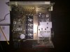
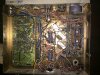
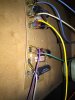
I need to read that again with an electronics dictionary next to me. But I have a few questions. What is a print? Would I just hook up a CD players AV cables to the chassis for the aux? I do have the TO-3 outputs I think. Btw, I replaced the caps that are on the opposite side of those outputs already. And when I test the channels, where do I do that from? I'm attaching some pictures I have on my phone. I won't be able to try anything tonight because I have duty and I'm stuck on the ship. Go Navy. But I'll try those things out tomorrow. And I really enjoy the experience of trying to get this thing to play right again. I'd rather fix it up here than send it anywhere.
 
Okay, I got a meter but couldn't figure out how to test those cases. I just read online I'll need to remove them from the board to test. I'll do that tomorrow.
 
Turn it on. Put one meter lead on the metal chassis. Just go to all four and write down the readings. Then we know which channel. YOU might know which channel it is by left and right, but WHICH PAIR of transistors is that ?

It is important that you leave the working channel working so you can compare as you go along.
 
Well, from top to bottom I got: 20.2, 40.2, 40.2, 19.6. Tried them all twice and it was consistent. Is that enough of a difference to affect it in the way it has?
 
Get a Dropbox account. It is great, not intrusive in your system, simply syncs. And you can sync other PCs to it. Put files you want to share in the public directory and right click to >Copy Public Link. Once you got that it can be dropped into any internet post, email or whatever. YOU are hosting it do it does not depend on anyone else. You get two gigs for free.

If you don't want to go through that you can email them to me and I will Dropbox them. But really you should get your own because it is so useful. I heard about it from computer nerds, they used it as a repository for device drivers and little utilities they use to like to use. Now I find it can serve fast enough to stream video. Not super video but video good enough for the screen on your PC.

When you see a Dropbox URL, if it is in the public directory it will have a "/u/" in the URL. If not it is probably coming out of the picture directory and there are problems with that. Bottom line, just put the **** in the /public directory and be done with it.

T
 
Okay, here they are. I had Dropbox but couldn't figure out how to get them there from my phone. Just emailed them to myself from iBooks.

Also, I posted the voltages from the outputs. Not sure if you saw them.
 

Attachments

Not sure those links are working. Let me try a different format.
well,let me know if the PDF format doesn't open for you, but I cant change it. Those output voltages again are 20.2, 40.2, 40.2, 19.6. I replaced the rest of the caps I had ordered but then spotted three I missed. No change in play though. I tried the AUX source but even though there is an AUX option on the dial, I don't see the plugs for it, so I unplugged the turntable and hooked up my cd player there. It only drove the one channel. External speakers are silent on that channel also.
 
I got it, I downloaded it in fact. That kinda looks like a Sams Photofact, is it ? If so the circuit symbol numbers might not match what is on the board. But before we go there, there is one other test.

Somewhere on that chassis is where the speaker wires come out. Now that it has passed the basic DC voltage test we need to make sure the speaker wiring is right. If you can find where ir says L, G and R, those should be spade lugs with the wires going down to the crossovers. Reverse the L and R ones and make sure that now the other side plays. That is what we want to see. Assuming we are going to see that I will continue, but do confirm it before going in to dynamic testing, or whatever you call this. Realize that I do not troubleshoot like most techs.

Since you do not have a scope we got DC voltages and making connections. I was going to have you check the DC voltages at the blue wires off those transformers where they go to the board, but quicker troubleshooting happens when you take bigger chunks in the beginning. So logically a good point to start is the volume control. "Try to follow the wires and figure out a way to short the two sections of that together. In most amps that would not be the right place right now but in this one it is because it is about the halfway point. you test it there you eliminate a whole half of that circuit. Once we find out if it is ahead or behind that part, then we cut THAT part in half, which is probably not going to work out perfectly in practice, but close enough.

Off the volume control you can short one channel to the other because it is almost impossible to harm anything that way. There is no DC. One caveat about this, when you are checking the signal path (which we are) NEVER SHORT THINGS TOGETHER THAT ARE NOT AT THE SAME DC VOLTAGE. The volume control is at zero all over the place.

They put it in a weird position in the circuit, and they got the treble and timber controls apparently acting on the AUX out if so equipped. But not the bass.

Once this thing is working, I'll throw you some killer mods for this thing. That tone circuit is a mess. It is designed to feed a speaker system that had no intention of being flat response. the bass is usually overpowering and the bass switch just cuts it down. Then when you tun it up the loudness overcompensation goes away and there is no bass. That is how they wanted it to sound. I can show you mods that will fix all that so that you CAN get flat response when you want it and reasonable loudness comp (variable actually) when you want it. And then you have to modify the crossovers. It is a matter of lowering the value of the caps to the horns. you also may want a coil in front of the woofer. You kinda gotta screw around with it, but we'll get to that after the thing puts out on both sides.

If you can find a way, there are the three MAIN leads on the volume pot, short them to the corresponding side. You'll see the ground side is already hooked together, you want the other ones. And you want the three that are in a group, not the taps which are spaced away from the main terminals. Short the middle, and the tops and see if that other channel pops in. It is very possible you can do this with a screwdriver. Just don't break anything and don't let it touch anything else.

https://dl.dropboxusercontent.com/u/29948706/maggie.jpg

The green and red dots indicate what you are actually doing. That is a definitive test. If the dead channel comes back the problem is to the left on the print. If it does not, the problem is to the right. You cut it in half.
 
Jurb; I've got a 1967 Astro with the R214. There is a "Balance pot" on the chassis right next to the P.S. transformer. Have the OP Center it or make sure it's centered. This may be part of the problem or the whole thing. It will kill the volume pretty much completely when rotated to one side or the other.

ScreenHunter_261 Dec. 29 11.39.jpg

Larry
 
You see that the front balance is that funky type that boosts one side as it cuts the other.

The balance pot to which you refer I think is the FM balance pot. I am pretty sure he has the same problem on other sources. I'll relook at the print to make sure, but I think that is only for FM stereo.
 
Jurb; I've got a 1967 Astro with the R214. There is a "Balance pot" on the chassis right next to the P.S. transformer. Have the OP Center it or make sure it's centered. This may be part of the problem or the whole thing. It will kill the volume pretty much completely when rotated to one side or the other.

View attachment 666359

Larry
Thanks Larry. It's centered. I stumbled upon that early on and found out that turning it full to one channel was the only way to get full volume.
 
You see that the front balance is that funky type that boosts one side as it cuts the other.

The balance pot to which you refer I think is the FM balance pot. I am pretty sure he has the same problem on other sources. I'll relook at the print to make sure, but I think that is only for FM stereo.
Okay JURB, first off, I think that IS a SAMs. I got it off another post on here and he only posted those pages. And second, when I touch those leads together with a piece of wire, the other channel comes in loud and clear. So is there another way to cut what we have left in half?
 
Whoa now let me get this straight. You shorted those volume control terminals and the other channel came in ? That is good. You just cut it in half. Leave the outputs alone and all that, it is to the left. I am going to load the print right now... ... ...

OK, here comes the fun part. forget whatever the PC board might say on it, you must go by wha Sams is calling the parts. For the left channel, Q11 and 12 are the exact equivalent as Q16 and 17 on the right channel. There is one of those standup capacitor kind looking things that is common to both channels and Sams is calling that PC5. Should have 11 pins on it. Six is ground. Right in the middle that makes it hard to tell way is pin one. But that is not the end of the world.

I see you do have the Sams pictorials, so you can find Qs 11, 12, 16 and 17. We need the voltages off of those. If the voltages are the same for both channels, and especially if they agree with what the Sams says they should be we are in good shape. Great shape in fact because if the DC voltages are right the transistors as well as PC5 which is made out of unobtainium are all good.

If the voltages agree, C83 and 90 are the next test points. They will be found where the wires come from the selector switch. Like you jumped the volume channel to channel, jump there channel to channel, as long as the DC voltages are the same, or close like a half volt.

If the other channel does not pop in, you got caps in the circuit between the selector switch and the volume etc. If it does, the problem might be the selector switch. Now that is BAD.

In fact you should have a quick look at it first. First of all make sure it is not cracked in half. the wafers, they crack and move away from the screws etc that hold them together and no longer make contact. This is also repairable but a PITA. Another thing that happens is the part where the double flatted shaft goes through to drive it wears or gets torn up for some reason. It may have gotten hung up mechanically and someone decided to use force on it. this can be considerably harder to repair.

Bottom line, let's hope (you can pray if you want) that when you find C83 and 90, that the dead channel does NOT kick in when you short it.

If it does, order some epoxy, there is something wrong with the selector switch.

Hey, if nothing else you'll learn something that these little punks coming out of college will never know. In fact know what ? On SED there are a bunch of the few engineers left in this country. They are getting really old, like starting to hit 80 n ****. But they keep throwing money at them because the new grads simply cannot do the job. The oldsters do not want to pay the new grads anymore.

Anyway, even if the unobtainium PC5 is bad it is still fixable. The voltages will tell us what is needed, possibly with a few resistance readings. But it is time for the next test. The voltages.

IF the voltages are right then C83 and 90. Keep us posted.
 
Whoa now let me get this straight. You shorted those volume control terminals and the other channel came in ? That is good. You just cut it in half. Leave the outputs alone and all that, it is to the left. I am going to load the print right now... ... ...

OK, here comes the fun part. forget whatever the PC board might say on it, you must go by wha Sams is calling the parts. For the left channel, Q11 and 12 are the exact equivalent as Q16 and 17 on the right channel. There is one of those standup capacitor kind looking things that is common to both channels and Sams is calling that PC5. Should have 11 pins on it. Six is ground. Right in the middle that makes it hard to tell way is pin one. But that is not the end of the world.

I see you do have the Sams pictorials, so you can find Qs 11, 12, 16 and 17. We need the voltages off of those. If the voltages are the same for both channels, and especially if they agree with what the Sams says they should be we are in good shape. Great shape in fact because if the DC voltages are right the transistors as well as PC5 which is made out of unobtainium are all good.

If the voltages agree, C83 and 90 are the next test points. They will be found where the wires come from the selector switch. Like you jumped the volume channel to channel, jump there channel to channel, as long as the DC voltages are the same, or close like a half volt.

If the other channel does not pop in, you got caps in the circuit between the selector switch and the volume etc. If it does, the problem might be the selector switch. Now that is BAD.

In fact you should have a quick look at it first. First of all make sure it is not cracked in half. the wafers, they crack and move away from the screws etc that hold them together and no longer make contact. This is also repairable but a PITA. Another thing that happens is the part where the double flatted shaft goes through to drive it wears or gets torn up for some reason. It may have gotten hung up mechanically and someone decided to use force on it. this can be considerably harder to repair.

Bottom line, let's hope (you can pray if you want) that when you find C83 and 90, that the dead channel does NOT kick in when you short it.

If it does, order some epoxy, there is something wrong with the selector switch.

Hey, if nothing else you'll learn something that these little punks coming out of college will never know. In fact know what ? On SED there are a bunch of the few engineers left in this country. They are getting really old, like starting to hit 80 n ****. But they keep throwing money at them because the new grads simply cannot do the job. The oldsters do not want to pay the new grads anymore.

Anyway, even if the unobtainium PC5 is bad it is still fixable. The voltages will tell us what is needed, possibly with a few resistance readings. But it is time for the next test. The voltages.

IF the voltages are right then C83 and 90. Keep us posted.
Okay, my selector switch looks fine. No cracks or any wear and tear noticeable. Here are the voltages: Q11; e=2.4, b=2.5, c=7.2. Q12; e=7.0, b=7.1, c=9.8. Q16; e=2.2, b=2.3, c=6.8. Q17; e=6.6, b=6.8, c=10.8. It looks to me like 11, 16, and 17 are really close to the schematic. Q12's c is a bit off though. I tested them all twice and it was consistent. I didn't test 83 and 90 because I wasn't sure about these voltage differences.
 
Back
Top Bottom