• The move to the new server is done. There are some software and database maintenance updates in process. This has us passing the hat around to help out. We appreciate any donations. Seriously, even a dollar helps. The payment page may be found here - https://www.audiokarma.org/support.html

Manifesto SE ... a single ended tube amplifier project

happybear

New Member
Manifesto SE ... a single ended tube amplifier project by HB.

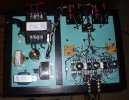
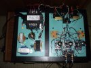
The physical layout is breadboard-minded, with exposed signal circuits connected to the power supply via umbilical connectors.

The power supply is a LOW DCR "flywheel" type with 250VA Hammond ICT as the main B+ transformer.

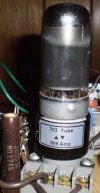
The signal circuit uses a 6SL7 with C4S active plate load capacitor coupled to 7C5 tetrode mode finals.

There is local feedback in the output stage for reasonable THD vs. power output.

THD = .44% @ 1W, THD = .90% @ 2W, THD = 1.50% @ 3W, THD = 2.30% @ 4W before clipping.

A schematic is pending further voicing of the circuit, mostly auditioning various coupling capacitors.

HB
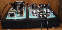
Manifesto SE front view Mundorf coupling caps.JPG Manifesto SE top view Mundorf coupling caps.jpg
 
Register to hide this ad
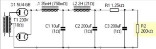
The Manifesto SE "flywheel" power supply:

5U4G rectifier is bypassed with UF4007 SS diodes. B+ will be around 300VDC.

Finals plate supply taken off C2. Finals G2, driver C4S taken off C3. R2 is a low current draw bleeder.

60Hz & 120Hz are about -85dB below the fundamental with this supply at all power output levels.

Noise free at idle, even when using high efficiency horn speakers.

HB used a similar PS configuration on a SE DC 6V6 breadboard amp project that ran flawlessly for over 5 years before it was recently decommissioned.

flywheel PSUD2.jpg
 
That's not a "flywheel" supply as it was originally described by the con man who "invented" it. Of course, no one really knows what a flywheel supply should be, because the concept has little or no engineering legitimacy. The schematic above is a simple CLC filter with a small choke added at the input to (potentially) reduce line noise. It includes a massive amount of capacitance, totally unnecessary in a small SE amplifier like this. I certainly believe it's quiet though. :)

Jack
 
That's not a "flywheel" supply as it was originally described by the con man who "invented" it. Of course, no one really knows what a flywheel supply should be, because the concept has little or no engineering legitimacy. The schematic above is a simple CLC filter with a small choke added at the input to (potentially) reduce line noise. It includes a massive amount of capacitance, totally unnecessary in a small SE amplifier like this. I certainly believe it's quiet though. :)

Jack
The first LC section is the "flywheel" part of the filter.

A builder needs to know why and how to select the component values properly for their application.

The rest of the filter values are chosen for reasonable AC ripple reduction needed so the SE amplifier can be used with high efficiency transducers like Altec horns or similar.

The amount of filtering can be reduced if more magnetic elements are introduced but that will add to the complexity and cost of the filter circuit.

This approach to SE tube amplifier filter design is 100% legitimate.

Comments about "con men" or whatever are simply baseless and without merit.

HB
 
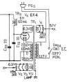
It's absolute BS, and the man who continually pushed the so-called flywheel (and its evil twin LSES) in everyone’s face for several years was eventually kicked off two major audio forums. Just search for those terms over at the Tube DIY Asylum. If you're patient, you'll find the posts from people complaining about poor performance. Akai powered a single 6BQ5 from the supply below in their early reel decks, and it's dead quiet with only 40uF of total capacitance. I know, because I'm listening to it with headphones as I write this. The addition of a small choke just after the rectifier isn't a bad idea, but it certainly doesn't create anything unusual or extraordinary.

Akai M7 PS.jpg

Jack
 
It's absolute BS, and the man who continually pushed the so-called flywheel (and its evil twin LSES) in everyone’s face for several years was eventually kicked off two major audio forums. Just search for those terms over at the Tube DIY Asylum. If you're patient, you'll find the posts from people complaining about poor performance. Akai powered a single 6BQ5 from the supply below in their early reel decks, and it's dead quiet with only 40uF of total capacitance. I know, because I'm listening to it with headphones as I write this. The addition of a small choke just after the rectifier isn't a bad idea, but it certainly doesn't create anything unusual or extraordinary.

View attachment 2922170

Jack
The "flywheel" filter was named by Henry Pasternak, an accredited EE who validated this approach to filter design years ago on another audio forum HB will not mention. There was also John Swenson, JLH and others who expanded the LOW DCR concept.

Your attempts to marginalize HB's efforts here will result in you being placed on "ignored" status, if this sort of offending behavior persists.

HB will ask you to refrain from posting any further comments on this thread. Enough already!

Only those who can contribute with a correct and positive attitude should post comments.

HB
 
Last edited:
Only those who can contribute with a correct and positive attitude should post comments.
Public posts in discussion forums invite opinions that might differ from yours or your design approach. I was personally involved for several years in detailed discussions regarding the "flywheel" theory and LSES, which is why I commented. And I have contributed to this thread with a reference to other discussions on this topic and with a commercial PS schematic that - like many others - works exceedingly well without a "flywheel" and without adding "complexity and cost" (your words). I've said my peace, and no one is forcing you to discuss it further.

Jack
 
That's not a "flywheel" supply as it was originally described by the con man who "invented" it. Of course, no one really knows what a flywheel supply should be, because the concept has little or no engineering legitimacy. The schematic above is a simple CLC filter with a small choke added at the input to (potentially) reduce line noise. It includes a massive amount of capacitance, totally unnecessary in a small SE amplifier like this. I certainly believe it's quiet though. :)

Jack

My only scratch-built single-ended project (see here: https://audiokarma.org/forums/index.php?threads/my-venture-into-the-world-of-se-amp-design.923539/ ) had what many people might call "gross overkill". Ripple is almost 131dB below max output level, according to PSUDII. High-speed diodes, then a 330uf first cap, then 1.5H 10 ohm choke, then 220uf cap, then another 1.5H 10 ohm choke, then a 100uf cap. Ripple is basically unmeasurable in practice. The amp- using parallel triode-strapped 6L6GC tubes in Class A2 SE, and Dave Slagle output transformers- puts out 10 watts at 20Hz, and 12 to 16 watts (16 ohms or 8 ohms load) broadband, with bandwidth out to 60KHz flat.

I don't regret using this "overkill" power supply, at all... the sound spoke for itself. Extraordinarily "fast", great soundstage, glorious midrange- while still having a very firm, powerful grip on the bass.

Regards,
Gordon.
 
Last edited:
The disagreement here is a legacy of the arguments about power supplies, which went on for many years over on Audio Asylum (the forum which HB refuses to mention, for those who don't know).

Those disputes made the Tube DIY board at AA what it is today - a sad place where days go by without a single post. I just looked and prior to a post that was made today, there had been no activity for 4 days.

It used to be a thriving forum with many knowledgeable and helpful participants. As I see it, the lack of action by the "moderators" played just as big a role as the individual who is often blamed.

His unconventional ideas sparked heated debate but it was his attitude that if anyone was building amps that followed established engineering guidelines, that they were doomed to failure and would end up with an amp that was "mid-fi at best" and probably worse. People got really tired of his "my way is the best" approach and his relentless proselytizing.

Fortunately, the mods at AK have made it clear that they will not allow such behavior here. That's why the person who was at the heart of the turmoil at AA was also banned here several years ago after he was either unwilling or unable to tone down his rhetoric.

Interestingly, today's new post on AA's Tube DIY board documents yet another forum (this time one in India) which also banned him a few days ago. That makes at least 6 forums where he has been banned, that I'm aware of, and there may be others.

As for the posts above, I don't really see anything that warrants an acrimonious exchange. Jack acknowledges that the use of a low value first choke could potentially help to reduce line noise. His issue with the the PS posted by HB seems to be that C2 and C3 are larger than necessary. So what. :dunno:
 
The "flywheel" effect is real; you can simulate it in PSUD. A small input choke and small cap following can increase voltage slightly higher than cap input while decreasing RMS current in the rectifier and power transformer - win-win. Values are critical, "tuned" to supply voltage and current. It does require a low-resistance choke and low ESR capacitor, and provides little filtering, so the same amount of filtering is required as for cap input. Probably not worth the expense unless you have the extra parts on hand.

The so-called "LSES" supply is a good way make an amp with excessive hum and poor power supply regulation...
 
I somehow completely missed the "LSES" discussions completely.

I went searching, and while there are a few hits from a few forums when "LSES tube power supply" is used as a search string- there's nothing that actually describes it from a technical standpoint.

Does anyone have a schematic for a typical "LSES" configuration, that shows what the topology looks like?

Regards,
Gordon.
 
I somehow completely missed the "LSES" discussions completely.

I went searching, and while there are a few hits from a few forums when "LSES tube power supply" is used as a search string- there's nothing that actually describes it from a technical standpoint.

Does anyone have a schematic for a typical "LSES" configuration, that shows what the topology looks like?

Regards,
Gordon.
If you really want to learn about "LSES", ask Dennis Fraker aka Tube Wrangler who still posts on AA.
Or Jeff Medwin, if you know someone who has his contact information or join HFV to see what he had posted there recently.

Good luck with your research and application.

HB
 
Returning to amplifier testing today.

Manifesto SE now operating in triode mode.

THD 1W 1KHz = 5.26% on PC FFT, mostly 2nd harmonic at -25dB below fundamental.

Changed OPT to Classic Tone 40-18031 SE 5K/8K: 4/8/16. Currently using 5K/8ohm taps.

Also added zobel network across OPT secondary, 50ohm + .1uF for added safety factor.

Also snubbed the diodes in PS with .02uF/2KV ceramic caps.

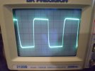
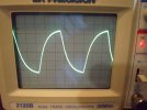
Bandwidth -3dB at 40Hz low and 22KHz high on scope.

HB will post schematic if subjective review is favorable.

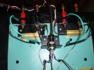
Manifesto SE with zobel on OPT.JPG Manifesto SE zobel on OPT close up.JPG
 
The disagreement here is a legacy of the arguments about power supplies, which went on for many years over on Audio Asylum (the forum which HB refuses to mention, for those who don't know).

Those disputes made the Tube DIY board at AA what it is today - a sad place where days go by without a single post. I just looked and prior to a post that was made today, there had been no activity for 4 days.

It used to be a thriving forum with many knowledgeable and helpful participants. As I see it, the lack of action by the "moderators" played just as big a role as the individual who is often blamed.

His unconventional ideas sparked heated debate but it was his attitude that if anyone was building amps that followed established engineering guidelines, that they were doomed to failure and would end up with an amp that was "mid-fi at best" and probably worse. People got really tired of his "my way is the best" approach and his relentless proselytizing.

Fortunately, the mods at AK have made it clear that they will not allow such behavior here. That's why the person who was at the heart of the turmoil at AA was also banned here several years ago after he was either unwilling or unable to tone down his rhetoric.

Interestingly, today's new post on AA's Tube DIY board documents yet another forum (this time one in India) which also banned him a few days ago. That makes at least 6 forums where he has been banned, that I'm aware of, and there may be others.

As for the posts above, I don't really see anything that warrants an acrimonious exchange. Jack acknowledges that the use of a low value first choke could potentially help to reduce line noise. His issue with the the PS posted by HB seems to be that C2 and C3 are larger than necessary. So what. :dunno:
Yeah, that place was flame war central for a decade or more. Between people getting banned and, sadly, people dying AA is a shell of what it used to be. Between the Jute/Lefevbre beef and Pasternack vs. seemingly everyone wars it was never dull. It was entertaining for a while but did get tiring. Ah, the good old days lol.
 
Back
Top Bottom