This is exhausting and silly. Maybe? Or maybe not? Valuable discussion.Wima 100u/500V is $30. Epcos 100u/450V is $38. Vishay 100u/450V is $42. There are dozens like this. Maybe the cheap ones are junk.
Jack


This is exhausting and silly. Maybe? Or maybe not? Valuable discussion.Wima 100u/500V is $30. Epcos 100u/450V is $38. Vishay 100u/450V is $42. There are dozens like this. Maybe the cheap ones are junk.
Jack

Epcos DC Link polypropylene film vs. Sanyo Oscon SP-series solid aluminum electrolytic.Aren't you doing a non-polar versus electrolytic bypass capacitor test?
If not, it's my mistake. Sorry.

It's all cool!Epcos DC Link polypropylene film vs. Sanyo Oscon SP-series solid aluminum electrolytic.
Any subjective review should be taken with a grain of salt.
The only way to know if something works for your application is to try it out.
HB

HB has scope and PC FFT for bandwidth measurements.Do you have a scope and signal generator for a FR check? If you have a good FR curve then that says you don't need any additional cathode bypassing. 40uF will cover just about any degenerative signal on the K. IF there is any it's in the frequencies @ 20Hz or lower and that will simply create a rolloff of the lower FR curve from the FB that remains unfiltered, if any. And if it does, it's actually a good thing, helping to create better low frequency stability of the amp.

That's only part of the story. A capacitor with high internal resistance can also produce a flat response. If that resistance is characterized by hysteresis or other non-linearities, signal quality will be compromised. The trick is to ensure there's an absolute minimum of signal AC at the positive end of the cap throughout the audible spectrum. That means it's bypassing the cathode effectively.If you have a good FR curve then that says you don't need any additional cathode bypassing.

Any signal voltage not bypassed by the cathode capacitor acts as a signal between grid and cathode. If it's distorted by hysteresis or other non-linearities characteristic to the cap, those anomalies will be transferred to the signal path. I don't know what you mean by "1% residual K signal," but I would always want the residual to be as small as is practicable for this reason.Don't wring your hands too hard over 1% of residual K signal. How much gain will that kill? Even if it is unbalanced across the 20-20K, it's not a material issue. This is OCD perfectionism. A cheap 50v. 50uF has @ 3R ESR. 1/2 that at 20KHz. Standard issue components. You can pay up for quality if it makes you happy or if you're just following the crowd. The sky isn't falling. If the cap is large enough to cover the spectrum, and if there is residual signal at all, if you add mini uF caps, and if they did anyting at all other than add to the total cap value, they would unbalance the rolloff by attenuating the highs of the FB only and tilt the amp's FR to the high side. It would still be inaudible even so.
OK, I see what you mean. I'm not sure how well that relates to bypassing as it might influence the G/K differential. For instance, if the grid is driven by 1V, what voltage will appear across the cathode RC using this theoretical cap? That's what is most important, and I suspect it really needs to be measured to be properly considered.In this amp the Kr is 290R. If the ESR of the full range cap is 3R, you have 99% of the signal bypassed. Like puting a 3R resistor under the "perfect" cap.

That's only part of the story. A capacitor with high internal resistance can also produce a flat response. If that resistance is characterized by hysteresis or other non-linearities, signal quality will be compromised. The trick is to ensure there's an absolute minimum of signal AC at the positive end of the cap throughout the audible spectrum. That means it's bypassing the cathode effectively.
Jack
There are two issues with all this in my mind. First, people often hear what they want to hear. I don't recall anyone claiming to have heard this effect who had performed valid A-B testing and/or made even minimal measurements such as distortion and frequency response. Second, to ensure this isn't merely the result of more effective bypassing, one would need to compare film VS electrolytic when the amplifier is already bypassed with a value selected on the basis of low frequency extension. I suspect that in cases where some effect can be verified, simply adding another electrolytic might provide the same result. I'll add that I've tested a number of electrolytics for response, and many are flat into the MHz region. On that basis, plus the inability to demonstrate this effect in my own gear by ear or with measurements, I'm pretty sure it's not an issue of frequency response.The degenerative FB signal created by the cathode resistor is dependant on the value of the resistor and .... all the other crap that determines the gain... I've not ever seen any rule of thumb to quickly figure that out. Or what's a typical range of ratios G/K ...? The dog ate my homework on that chapter.
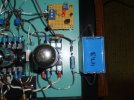
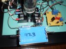
After listening to the Epcos 50uf 630V 10% as a cathode bypass capacitor for SE 7C5 finals for several evenings afterwork, HB deems it to be acceptable.It's all cool!
No, I understand about YMMV. Just curious in your opinion.