


You are using an out of date browser. It may not display this or other websites correctly.
You should upgrade or use an alternative browser.
You should upgrade or use an alternative browser.
Marantz 1515 lights / lamps....
- Thread starter kyle775
- Start date
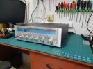
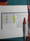

For the 19KHz on J140 do I need frequency counter or just with the 189 meter?

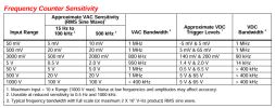
Looks like your Fluke 189 can measure the 19kHz, so you should be able to use that.
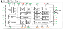
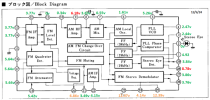
Also, I entered your measured Q206 voltages onto the chip functional diagram (below) and most look OK. I think some are a little high but it may be because your Vcc on pin 23 is 12.48v vs 11.6v. The one measurement that looks odd is pin 5 at 0v when it should be 5.3v. Can you check to make sure that C229 (1000pf) is not shorted?
EDIT: If the 19kHz is there but slightly off of frequency, it looks like you can adjust R326 for 19kHz. Mark its current position with a marker then try tweeking it a little to see if the stereo carrier will lock-in.

Also, I entered your measured Q206 voltages onto the chip functional diagram (below) and most look OK. I think some are a little high but it may be because your Vcc on pin 23 is 12.48v vs 11.6v. The one measurement that looks odd is pin 5 at 0v when it should be 5.3v. Can you check to make sure that C229 (1000pf) is not shorted?
EDIT: If the 19kHz is there but slightly off of frequency, it looks like you can adjust R326 for 19kHz. Mark its current position with a marker then try tweeking it a little to see if the stereo carrier will lock-in.
Last edited:
Bingo! C229 is shorted. This cap is film cap. Is it OK to replace it by monolith ceramic cap?
Last edited:
Ok thank you. I'll try and let you know if it resolved the problem.
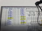
Ok. I put 1.2nF ceramic cap on C229 in this position only for testing and the stereo light doesn't light up. Here's the new pinouts test results. Pin #5 is now 5.26V
Attachments



Last edited:
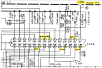
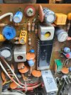
Ok. So I got 50Hz
No. 50Hz with 1.7V. Strange when I touch the positive lead with my hand or without (ie open) it gives also 50Hz but 0V. When I take it away from the receiver the meter read about 10Hz
Last edited:

Yes to the chassis
Ok. When put the black to J104 it gives 22KHz
Now the 189 and 87V read the same 22KHz. What does it mean?
Last edited:
