


You are using an out of date browser. It may not display this or other websites correctly.
You should upgrade or use an alternative browser.
You should upgrade or use an alternative browser.
Marantz 1515 lights / lamps....
- Thread starter kyle775
- Start date
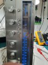
Yes the voltage on pin 2 rises to 9.3V on stereo and drop to 0V when no stereo. The sound is also stereo. Thanks again. I really appreciate your assistance.
I've already ordered the 1000pF film cap a good one for C229. Do think it's OK to leave the 1000pF ceramic the blue one that put or to change it when it arrives?
Last edited:
Ok. Thank you.
Hi, later of the 1515 I've tried to look for the bais and offset setting on the service manual but didn't find any thing about that.
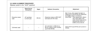
I think I understand how measure the bias but it talks about DC voltmeter of 100/50mv ranges on R741 (R743) and R742 (R744) putting the DC voltmeter in parallel on those resistors and after that it says 10mA. Is it a mistake and should be 10mV?
About the offset do I need signal Gen with 20KHz in the AUX and putting a 4ohm resistor (let say 50W) in the output speakers. But what is it the distribution meter that should be also plug in to the speakers in parallel to the resistor? Is it a scope?
About the offset do I need signal Gen with 20KHz in the AUX and putting a 4ohm resistor (let say 50W) in the output speakers. But what is it the distribution meter that should be also plug in to the speakers in parallel to the resistor? Is it a scope?

I don't know the answer to your first question. A little confusing.

Method 1:
Attach a signal generator to the AUX input and set to generate a sine wave with a frequency of 20kHz.
My interpretation is you attach a 4 Ohm resistive load onto the speaker terminal, then connect the distortion meter to the same speaker terminals.
You then need to measure and set the volume control for an output voltage for a 0.25 Watt.
It is NOT a distribution meter, it's a distortion meter. Something like this. It also has a low noise frequency generator. Set it to 20kHz on the AUX input.But what is it the distribution meter that should be also plug in to the speakers in parallel to the resistor? Is it a scope?
Method 1:
Attach a signal generator to the AUX input and set to generate a sine wave with a frequency of 20kHz.
My interpretation is you attach a 4 Ohm resistive load onto the speaker terminal, then connect the distortion meter to the same speaker terminals.
You then need to measure and set the volume control for an output voltage for a 0.25 Watt.
P = V x I
P = V x (V / R) = V^2 / R
V = SQRT(P x R),
V = SQRT(0.25 W x 4 Ohm)
V = SQRT (1)
V = 1 Volt
Last edited:
Yes sorry it is distortion meter. The speller put a wrong word and I didn't notice. I've already assumed that I don't have this meter. So.. There's no offset adjustments and this is instead of the offset? What about the bais is it 10mA or 10mV? Thank you.
Last edited:
EDITED:
This is what I found searching for how to set the offset.
https://audiokarma.org/forums/index.php?threads/marantz-1515-dc-offset-bias.530943/
He basically says to adjust bias, measure the voltage across R741 and adjust R717 until it reads 4.7mV.
This looks like it is the equivalent of 10mA of current through R741.
Do the same for the other channel.
Connect meter across R743, power on, adjust R718 for 4.7 mV DC.
This is what I found searching for how to set the offset.
https://audiokarma.org/forums/index.php?threads/marantz-1515-dc-offset-bias.530943/
He basically says to adjust bias, measure the voltage across R741 and adjust R717 until it reads 4.7mV.
This looks like it is the equivalent of 10mA of current through R741.
V = I x R
I = V / R = 0.0047 V / 0.47Ohms
I = 0.01 A = 10 mA
Power off, use a marker to mark the current position of the variable resistor, connect voltmeter across R743, power on then adjust R718 to 4.7 mV DC.Do the same for the other channel.
Connect meter across R743, power on, adjust R718 for 4.7 mV DC.
Last edited:
So it's 4.7mV across the resistors. It's not clear and a bit confusing by the service manual. What about the R742 and 744 that are mentioned in the service manual ? In the schematic it seems that 741+743 are on one channel while VR-R717 is for that channel and 742+744 on the other channel and VR-R718 is for other channel. From the link there is no DC offset adjustment. Thank you.
Last edited:
You are right. (Also, I had an error in my previous instructions above)
Let's try this again:
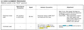

Let's try this again:
- Power off, attach voltmeter across R741 (or R743). Power on and adjust R717 until the voltage across R741 = 4.7mV (= 10mA).
- I think the voltage across resistor R741 and R743 should read close to the same. You can try this with your existing setting to verify.
- Power off, attach voltmeter across R742 (or R744). Power on and adjust R718 until the voltage across R742 = 4.7mV (= 10mA).
- The voltage across resistor R742 and R744 should be close to the same. (I think?) Verify with you existing settings.
Ok I will try it and let you know. Thank you.
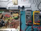
Ok. Results. When I put 2 meters 1 on R741 and 2 on R742 and adjust the R717 for R741 and R718 for R742 I got 2.4mV on both channels. When I moved the meters 1 to R743 and 2 to R744 I got close value but negative. When the values are the same in positive they are a bit different on negative.
Attachments

Last edited:
BTW The sound of this 1515 not bad at all considering the model and of course the age (the stereo of the Golden age of 70's and 80's are built with good quality parts and good design) i.e no parts were changed on this receiver except one small cap for the stereo (THANKS TO YOU dankik, I don't know your name) the tonality and the balance on this receiver are good with good bass and treble without Loudness and tone control are in zero. By listening with headphones.
Last edited:
I bought this receiver in trash condition with $120 everything was dirty, the knobs, front panel and and all around the case. The flywheel of the radio was broken and there were no light at all. All the pots and switches on the front panel were nosie and alot of dust inside. Now it's like new. Pity that I didn't took pictures before.
Attachments
-
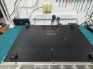 20241205_235334.jpg104.8 KB · Views: 3
-
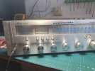 20241205_130821.jpg103.2 KB · Views: 3
-
 20241205_131016.jpg97.4 KB · Views: 3
-
 20241205_130857.jpg105.1 KB · Views: 3
-
 20241205_130849.jpg115.9 KB · Views: 3
-
 20241205_130834.jpg102.4 KB · Views: 3
-
 20241206_133513.jpg127.9 KB · Views: 3
-
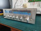 20241206_133647.jpg129.2 KB · Views: 3
-
 20241206_133652.jpg136.6 KB · Views: 3
-
 20241202_195553.jpg133.9 KB · Views: 3
Last edited:
I think you want to get 4.7mV (not 2.4mV) across R741 or R742 to get 10mA of current? Were you not able to adjust to this value?I got 2.4mV on both channels.
The negative values being close should be OK.
BTW, it looks great... cleaned up nicely!

Last edited: