• Please note that Audiokarma will be offline briefly for updates early on Monday morning, September 28th.

Marantz 1515 lights / lamps....

Wow.. Yes you are right. I don't know from where I got this value but I will fix it right away. Thank you.
 
Last edited:
Correct it to 4.7mV but these are the negative values.
 

Attachments

  • 20241208_205446.jpg
    20241208_205446.jpg
    143.3 KB · Views: 4
  • 20241208_205450.jpg
    20241208_205450.jpg
    158.1 KB · Views: 4
  • 20241208_205606.jpg
    20241208_205606.jpg
    162.9 KB · Views: 4
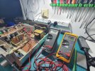
I don't know if that is right? I think what it means is that you have a slight positive voltage bias which I think would help in the switching from positive to negative part of the waveform minimizing the 0 point crossover distortion? If you set the offset to the negative values by making the neg voltage equal to 4.7mV, I think it achieves the same purpose to move the zero crossing switchover off of 0v. Does it sound any different? I tried to find another receiver in the same family, but the next one up 1520 has the same instructions and the 1550 has a different discrete Main Amp board.
 
Anyway this is what I get if I set the offset in the negative.
 

Attachments

  • 20241208_214136.jpg
    20241208_214136.jpg
    178.1 KB · Views: 4
  • 20241208_215157.jpg
    20241208_215157.jpg
    176.4 KB · Views: 4
Last edited:
Ok. Anyway. Thank you for everything you did for me till now I really appreciate you help and accept my apologies if I said something wrong because I don't think that I did.
 
BTW Sensei in Japanese or Chinese it's a title of honor and respect to someone who is teaching you.
 
My heritage is 3rd generation Japanese so I am aware of Sensei.
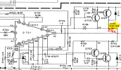
This may be getting more technical than you want, but I looked up the part for Q701/Q702.
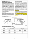
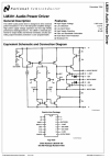
FYI, this is the amp that is used in your Main Amplifier, LM381. If you compare the typical application on Page 2, it looks very similar to your amplifier.
The LM391 drives the pair of transistors for the output.
Note that there are two resistors RE and RE' which corresponds to your R741/R743 on your board.
On page 7, the paragraph describes how to adjust "bias current" by measuring the voltage across resistor RE. It says to adjust "RB" on Figure 1 to provide about 25mA of current. We calculated 10mA = 4.7mV, so we can actually go a little higher (according to the datasheet).

Recommendation: I would go back to your original adjustment of 10mV across the resistor R741 and R742 and leave it at that.
1733689958556.png
1733690065025.png
1733690362562.png
1733690181039.png
1733690589702.png
 
Thank you for your reply. Wow.. It seems nearly the same. The Q701/Q702 on my receiver are LM391. So you mean that the service manual meant 10mV instead of 10mA?
 

Attachments

  • 20241208_231808.jpg
    20241208_231808.jpg
    175.9 KB · Views: 3
Last edited:
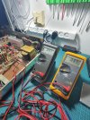
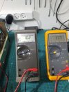
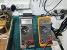
Ok. I've set it to 10mV also attached the negative voltage.
 

Attachments

  • 20241208_234314.jpg
    20241208_234314.jpg
    124.8 KB · Views: 2
  • 20241208_233922.jpg
    20241208_233922.jpg
    132.9 KB · Views: 2
That should be fine (about twice what you had before when you had it set to 4.7mV) but about what the chip app note says.
 
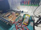
By the datasheet of the LM391 25mA should give11.75mV. I've tried to figure out the temp before and after the changes on some of the parts on the board like the resistor and the transistor with heatsink in the attached pictures and the deferences is few degrees. Again, do you think that there's an error in the service manual and instead of 10mA it should be 10mV? Thank you.
 

Attachments

  • 20241208_233558.jpg
    20241208_233558.jpg
    157.7 KB · Views: 2
  • 20241208_233506.jpg
    20241208_233506.jpg
    179.1 KB · Views: 3
Last edited:
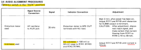
Based on what we now know, I would think that the SM has an error. The procedure says to use a Voltmeter and a specific voltage range setting, but the adjustment value seems to have the wrong units. The NS LM391 datasheet instructions for adjusting the bias current to 25mA seems to match the value of 10mV pretty closely. I would keep it at 10mV across the resistor.
1733761816646.png
The Also, when taking the voltage measurement, make sure the selector is in AUX and volume control is turned all the way down.
1733760010708.png
 
Last edited:
Yes that's right! And yes of course it was all the time on zero volume and on AUX when nothing was connected in the inputs. That's why I wrote this question on thread #50 if it's 10mV instead of 10mA. Thank you very much for your help.
 
Last edited:

Attachments

  • 20241209_214740.jpg
    20241209_214740.jpg
    95.5 KB · Views: 2
  • 20241209_214641.jpg
    20241209_214641.jpg
    177.6 KB · Views: 2
  • 20241209_213628.jpg
    20241209_213628.jpg
    177 KB · Views: 2
Back
Top Bottom