• The move to the new server is done. There are some software and database maintenance updates in process. This has us passing the hat around to help out. We appreciate any donations. Seriously, even a dollar helps. The payment page may be found here - https://www.audiokarma.org/support.html

Marantz 2216 recap

varox84

Active Member
Hi guys, Im recapping a 2216 intended as a gift when I finish. This is my second recap project and, having learned from the previous, I am now doing one board at a time, checking whether it works then moving on.

I just finished recapping the power supply board but when I tested it, to my surprise it sounds really bad, distorted and with low volume. Funny enough, if I leave the source playing and I turn the amp off then it sounds ok for a short second before the amp turns completely off. The same happens when I turn it on with the source playing, it sounds perfect for 5 seconds and then it starts distorting.

I only changed the capacitors on this board, nothing else. Important is that the unit worked before me being there. Does this sound like a faulty cap from the ones I replaced? I'm pretty sure the polarities are correct. Would appreciate any help.

Thanks!
 
Register to hide this ad
I'd recheck polarities as a starting point- if that's all you touched. Is there a voltage adjustment for that model?
 
I will re check polarities. I dont know if there is a voltage adjustment, will check.
I have to add that this distortion does not happen when I use the tuner. Any ideas on why suddenly sounds ok at turn on-off?
 
No idea, maybe from a reversed cap? You can't rely on the silkscreens, when I recap I do one cap at a time and make note in my head of its orientation unless it has a matching cap, then i'll pull both remembering the orientation.
 
The only adjustment on the receiver is idle current.

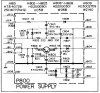
Have a look at the schematic. There are several points you can test with a DMM and see if the board is producing correct power rails.
ImageUploadedByTapatalk1365890988.808016.jpg
 
checked the polarity with the pictures I had made, they are the same as now and the same as the manual. Its probably a faulty cap, but how do I tel which one?

And it does not work with the tuner, I only thought it did.
 
Use your DVM and check for continuity for each leg you soldered on, go to something else on the same trace see if all is well. You may have a cold/bad solder joint.
 
I will check for continuity. I dont know how to check the voltages. Should the amp be on or off? Can you give me an idiot proof example of how you would use the DVM on that schematic? Thanks a lot
 
Got clip leads? Black to ground (chassis) , meter set to DC and clip red to each of the jumpers and lead of each leg of the transistor and record your results.
 
Got clip leads? Black to ground (chassis) , meter set to DC and clip red to each of the jumpers and lead of each leg of the transistor and record your results.

If you don't have clip leads put your black (-) probe on the chassis ground and tape the red (+) probe except for the tip to prevent accidental touching. With amp powered up on wall current check each of those above listed points and record the actual versus schematic values.

This is a skill you should learn before even touching a soldering iron. It is essential to any repair or restoration work. Do the above and you will track down the little bugger.
 
Ok, here they are.

H801 (B)= 32,8 (should be 35,7)
H801 (C)= 42,2 (should be 43,5)
H801 (E)= 32,2 (should be 35)

J808= 50 (should be 52)

J811= 32,3 (should be 33,7)

J813= 14 (should be 14)

J814= 9,3 (should be 10)

Al values except one differ by 1v or so from manual values... so whats next?

As always, thanks a million.
 
Last edited:
Bracket non/ bracket are usually stereo vs mono voltages- j814 is the feed for the stereo lamp. C810 and H808 are the 2 components in that circuit. Is the stereo lamp functioning?
 
Last edited:
Stereo lamp works ok, and the values measured ok, right? so can it be that there is a faulty cap and the values still measure ok?
 
I see voltage on J814, i had measured it wrong, these are the values:


H801 (B)= 32,8 (should be 35,7)
H801 (C)= 42,2 (should be 43,5)
H801 (E)= 32,2 (should be 35)

J808= 50 (should be 52)

J811= 32,3 (should be 33,7)

J813= 14 (should be 14)

J814= 9,3 (should be 10)

Al values except one differ by 1v or so from manual values... so whats next?
 
Back
Top Bottom