• Please note that Audiokarma will be offline briefly for updates early on Monday morning, September 28th.

Marantz 2325 PU01 Multipath and Speaker Relay Short

richardg0n

Active Member
tempImageZTGmPI.png tempImageQguGKp.png IMG_3840.jpg
Hi Guys,
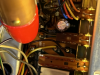
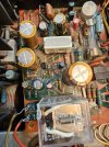
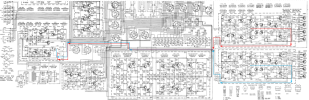
My 2325 lost the right channel while playing music. Pushing the hi and low mutlipath buttons brought back the right channel temporaily. I decided to DeOxit the switches and pulled out PU01. The right channel output retuned and reinstalled PU01. The right channel again stopped working when I reinstalled. I had previously recapped and changed all transistors on PU01. Here are my findings so far while connected to DBT.

  • The speaker relay only engages while plugged into DBT.
  • Speaker relay does not engage when I plug into my Variac @120VAC.
  • Swapped Pre(PE01) from another 2325 and no change. Reinstalled original Pre.
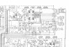
  • I have a signal tracer and signal generator and fed 1k sine wave tone to AUX. Verified signal output on PU01 pin 13 and 14 while speakers are not switched on.
  • Good signal on pin 13 and 14 until I engage switch on Main SU01-8 and Remote SU01-7. Then only Pin 13 work and Pin 14 loses signal when Main speakers switched on.
  • Losing signal at pin 13 and 14 when Moving balance to the right.
  • Checked and reflowed solder points on P01 and no change.
Thank you for your input
 

Attachments

  • PU01 schematic.jpg
    PU01 schematic.jpg
    160.4 KB · Views: 26
Last edited:
Register to hide this ad
Suggest you cross-connect the left and right channels by using the main in/pre-out jacks to see of the problem follows the right pre-amp to the left channel and vice-versa. This should determine if the issue is in the right power amp or the right pre-amp. If the problem persists on the right channel then it will indicate a problem with the right power amp module. If it migrates to the left channel then it is an issue in the pre-amp. Since you swapped pre-amp modules and the problem persisted I am betting there is an issue with the right power amp module. Also, are your main and remote speakers 8 ohm? if both are connected you are running into a 4 ohm load, if they are not then you could be overloading the power amp.
 
Suggest you cross-connect the left and right channels by using the main in/pre-out jacks to see of the problem follows the right pre-amp to the left channel and vice-versa. This should determine if the issue is in the right power amp or the right pre-amp. If the problem persists on the right channel then it will indicate a problem with the right power amp module. If it migrates to the left channel then it is an issue in the pre-amp. Since you swapped pre-amp modules and the problem persisted I am betting there is an issue with the right power amp module. Also, are your main and remote speakers 8 ohm? if both are connected you are running into a 4 ohm load, if they are not then you could be overloading the power amp.

I have two 8 ohm 200w resistors connected to the main output while testing.

Cross-connected Pre/Main jacks and found right main to be the source of problems . Swapped out right amp from another 2325 and the receiver is working.

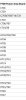
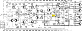
Regarding the bad amp, I previously recapped and changed transistors on the main board(see attached pic for list of parts). I’m thinking of testing the output transistors and then moving over to signal path transistors.
 

Attachments

  • 0BD41B8D-F9DC-4CB0-9BC7-D64B15477D04.jpeg
    0BD41B8D-F9DC-4CB0-9BC7-D64B15477D04.jpeg
    37.2 KB · Views: 28
I recently restored a 2325 and completely re-built the P700 boards with the exception of the output transistors. Here is a link to the thread I posted, it may be helpful. It looks like you did pretty much what I did to the P700 boards in terms of restoration.
Your approach to testing the P700 board is good, If the Output transistors have failed they may have taken some of the drivers behind them out also, good to check them. The fact that the channel "came and went" may indicate a thermal connection issue, maybe a suspect solder connection?


https://audiokarma.org/forums/index...restoration-and-looking-for-guidance.1011940/
 
I'm not sure if it helps, but I had a similar issue with the 2325 I'm working on. One of the channels would occasionally cut out. In my case, the metal cover between the solder side of the PU01 board and lamp housing was occasionally making contact with something on the PU01 board. I trimmed the leads down another notch and covered the bottom side of that cover with kapton tape and the issue was resolved.
 
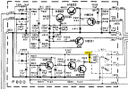
sorry, I will have to ask this, what does R840 do? I did some replacements on the P800, now the relay clicks - but no speaker have no sound output.
 

Attachments

  • KakaoTalk_20240703_171342636.jpg
    KakaoTalk_20240703_171342636.jpg
    174.2 KB · Views: 13
sorry, that was my bad. it is R740 on the power board. R713 adjust the bias, can't find info on the R740. Thanks for notice my mistake.
 
the other question I need an answer for is where does the signal come from before the relay connects it to the speakers?
 
A couple of issues I have run into on this and other similar Marantz models. The internal contacts in the main to pre amp problems where insertion of a patch cord or jumpers are needed. Also the connector on the back of the tone board being funky and needing serious cleaning. *Do not loose the little plastic lock*
 
I was attending a convention the last 4 days. Sorry for late thanks. I am starting to renew caps and transistors. I started with the power supply board and already screwed up a bit. I think I will come back here every so often. Really
 

Attachments

  • 20240709 - perplexed.png
    20240709 - perplexed.png
    8.1 KB · Views: 6
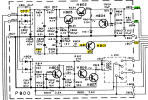
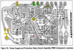
Hi guys, I am back with a cute question. on the 2325 P800 there is a H812. What is it and what does it do? How could I test whether it is still good? And by the way, I am sorry for late introduction. I am 78 year old hobbyist and I live in South Korea. It is a hassle to get parts, like diodes and resister shipped here. Thanks
2325-P800 _20240711_2248.jpg
 
H812 is a "flyback" diode. It is connected across the relay coil and its purpose is to prevent voltage spikes from the collapsing EM field when the relay coil is de-energized.
You can test it by unsoldering one end of the diode then use your DMM set to Ohms. Connect the DMM leads in forward bias and it should show low ohms, connect it in reverse direction and it should show an "open" connection.
Hope this helps.

1720708616988.png
 
I following those leads, great help. My next question is something like this. Where do the 14 vol of P800 J07 come from? I don't get it on my receiver.
 
Where do the 14 vol of P800 J07 come from? I don't get it on my receiver.
Did you mean "J807"?
The 14VDC is generated from transistor H801. There could be a number of reasons why it is not there.
  1. Check the voltages of transistor H801:
    • Emitter = 14V
    • Base = 14.6V
    • Collector = 35V
  2. The 35V comes from diode rectifier H808. Check the voltage at R801, 150ohm resistor
  3. If you have correct voltages on H801 base & collector, but not 14V on the emitter then H801 may be bad
  4. If you have 14V on H801 emitter, but not on J807, then check the circuit board traces for an open. With power off you can check continuity from H801 emitter to J807.
  5. Do you have the other voltages?
    • J805 = 35V
    • J806 = 19V
  6. You can use J804 for your DMM ground or use chassis ground
1721048574611.png

1721049059839.png
 
Thanks a lot. I had this Marantz 2325 receiver since 1978, when I got it second hand from the first owner. I use it with a AR 3a, European improved version and it sounds just gorgeous. It began showing its age, so I got two separate restore kits and started restoring with the power supply board P800 and I plan to go through the all caps and transistors except the power out transistors.
The help from you guys in this forum is just what I need to complete this project. I only hope I will not mess up. I made myself a large schematic using 15 letter sized sheets taped to make all connections easier to see.
I really appreciate your help and the kind way you are offering these explanations.
 
When you start to replace parts... DO ONE BOARD AT A TIME, then test to make sure it still works. Then go on to the next board. That way if you screw something up, you know where to start to look. Do them all and it will be difficult to find.
I am assuming that it works now, correct? If it does, yes start with the P800 board. I would do the caps first, test, then transistors.
When you are changing electrolytic capacitors, I take a permanent felt tip pen and put a small dot on the top of each capacitor on the side that faces the "front" of the receiver.
This does two things:
  1. It shows if you forgot to replace any caps since there may be some still left with dots
  2. Sometimes the PC board cap polarity silkscreen markings are wrong. With the dot on the cap, you can look to see the orientation of the cap that you removed to double check the installed new cap polarity.
Take your time. When de-soldering components, it helps to use either a solder removal tool or solder "braid" to remove the old solder. Do not pull too hard on the cap you are removing because with these old boards you could damage the copper foil on the board. Before installing the new component, clean the solder pad with 97% isopropyl alcohol and a Q-tip cotton swab. It also helps to make a "clean" new solder joint if you apply some solder flux to the pad before soldering. Clean off the excess flux with Q-tip/alcohol after soldering to prevent future corrosion.
 
Back
Top Bottom