• The move to the new server is done. There are some software and database maintenance updates in process. This has us passing the hat around to help out. We appreciate any donations. Seriously, even a dollar helps. The payment page may be found here - https://www.audiokarma.org/support.html

Marantz 2325 PU01 Multipath and Speaker Relay Short

Hello Folks.
This is getting quite confusing to me, but I appreciate all the help and recommendations as well as corrections on my ailing 2325 receiver. Per the attached Excel file I want to update my report on the P700 boards. IS there anyone out there able to make sense, of these voltage numbers? These numbers are giving me a headache. Thanks for your 'kind' reply.
 

Attachments

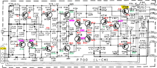
A couple of comments starting with the L-channel P700 for now.
  • I transferred your voltage measurements from the table onto the P700 schematic
  • The voltage measurements in magenta are probably not correct because your measurement on the same schematic line has the opposite polarity (+/-), please check
  • Notice that the two ground segments on the left and right half of the schematic (dark line) are not connected. @rBuckner commented in another post that you need to have the RCA jack (J701) plugged in to complete the ground connection. Did you have it plugged in when you measured the voltages?
  • Where did you connect the (-) lead of you DMM when you measured the voltages?
1727028310726.png
 
Thanks for your hard work in figuring out this mess. Yes I got a gender to connected the RCA jacks correctly. I have connected the black lead of the DMM to the bare metal part of the chassis. I checked the in circuit value of all resistors for the right channel, most of them are close or exact to the value shown on the schematic but a few are very different. I will proceed with the left channel and then order a bunch of the resistors with bad values. Once I finish that, I will put that report here and also update the transistor voltages for the left channel. On the right channel I replace The H708 - H709 transistors but put the originals in for H706 - H707 (the replacement transistor would need to cross the E-C-B legs as the board has it E-B-C). On the left channel I have replaced the H701-H702 pair, and H703 - H705 as well as H710 - H712 and H711 - H713. (I will get back this evening, Korea time.)
 
Here are the R channel voltages. Again, the magenta-colored ones are the same signal and do not match. Please check.
  • H704(c) and H705(c) are connected together, but have different voltages
  • H713(b) and H711(c) are connected together, but have different voltages
  • H708(c) has a (-) voltage, did you measure it correctly? It should be positive
1727068971596.png
 
Last edited:
Back
Top Bottom