• The move to the new server is done. There are some software and database maintenance updates in process. This has us passing the hat around to help out. We appreciate any donations. Seriously, even a dollar helps. The payment page may be found here - https://www.audiokarma.org/support.html

Marantz 4400 no lights.....?

Could it be a defective transistor on the PE01 board that is causing the blending? I will try to trace the RIGHT front AUX input signal to the PE01 board and see where it goes from there.
When looking at the PE01 board......how are the channels positioned? LR-LF/RF-RR? Ie, the front channels in middle of the board?
 
I'm not sure how a failed transistor can cause a bridge between channels, it's physically impossible. The 4400 sections are split into 4- they are totally seperate, the only think that could combine a signal between a right and left channel is a mechanical error- solder bridge, switch, miswired something or other- even down to a broken wafer. The only time audio signals are combined is by the 2x4 / 4x4 switch or perhaps the mode switch- that would do it. If you injected a signal and see the bridge leaving the pre then you'd know it's before the pre- have you narrowed it down at the pre? Have you plugged the pre into another amp to see if the sound is bridged? A scope would lead you down the garden path, it's hard to troubleshoot without being able to see what's going on.

Honestly this sounds to me like a broken wafer on a switch or a bent contact.
 
Last edited:
Ok...bk.....broken wafer.......damn...that would be some operation! BUT, if it was a broken wafer.....wouldn't it affect ALL channels? My problem is with the fronts only.
I used a Marantz 1070 to test if it was the pre or the amps........it was the pre...or somewhere before it.

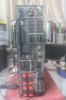
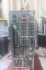
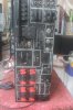
Here are a couple of pics of the rear. The jumpers should be mounted correctly! CHAWAAH!

I need to build a primitive audio signal probe................a scope is expensive!
 

Attachments

  • IMG_5165.jpg
    IMG_5165.jpg
    65.1 KB · Views: 25
  • IMG_5166.jpg
    IMG_5166.jpg
    59.6 KB · Views: 21
  • IMG_5167.jpg
    IMG_5167.jpg
    76.5 KB · Views: 20
Yup, jumpers look good. Too bad you weren't close, I have 3 scopes.

Not necessarily- depends on where the metal broke. The metal on the wafers can split, bend pins, cause bridges- i've seen it- my sansui eight was doing weird stuff till I found the broken switch.
 
Ok.....lets hope it isn't a wafer on a selector...............that would be awful! The weird thing is that it is only the front channel inputs that are affected.
Is there ANY possibility of the signal getting blended on the PE01 board? I have checked all the solder with a loop....it looks good.

I better get my act together and get a scope.......some digital o'scope......Siglent, Owon, Rigol......just need something reasonable and durable...............not to big..
 
When looking at the block diagram in the UM, the blended signal must happen BEFORE it leaves the PE01 board. After the PE01 board the signal goes to the scope....which indicates only mono-sound.

After the PE01 board the signal also goes to the volume, balance, filter and phase....but the 'blending' must happen before this.

So....we are left with a problem on the PE01 board .....or a defective selector switch..?
SAhucks....i feel i am pretty close to solving the issue...........IF it is a selector, then we have A BIG problem.......................
 
I just got hold a BK 3001 audio generator...........it has a red and black output. Is this 2 outputs or is the black ground?

I am going to give in.........I will invest in a scope......new Rigol DS2000 series looks to be excellent. It will afterall be a longterm investment!
 
Last edited:
The PE01 board has the Diode Matrix.... Gee how time have I said diode matrix.....


When looking at the block diagram in the UM, the blended signal must happen BEFORE it leaves the PE01 board. After the PE01 board the signal goes to the scope....which indicates only mono-sound.

After the PE01 board the signal also goes to the volume, balance, filter and phase....but the 'blending' must happen before this.

So....we are left with a problem on the PE01 board .....or a defective selector switch..?
SAhucks....i feel i am pretty close to solving the issue...........IF it is a selector, then we have A BIG problem.......................
 
The PE01 does not have the diode matrix. The diode matrix is on the PF01 board.

Anyway........as I understand it......the audio signal just goes through the diode matrix for scope representation. It has nothing to do with my 'blending' problem.

Also....all sk30's and diodes have been changed. The diode matrix works fine as I see it. It is correctly representing my 'blended' front channel signal.
 
Whoops .... You're right.... On the physical Location. But electrically it's in the middle of the PE. Diode matrix gets it's signals from the early stages of the PE.

As you are suspecting some thing is wrong on the PE and if I remember you did some work to the Diode matrix, which is a lot more than a few diodes.

The purpose of the diode matrix is to "blend" the 4 channels into horizontal and vertical signals. A mistake on the input FETs on that board can propagate back to the PE. And if I remember , all four channels are "crammed" together really close on that board. All the input pins are right next to each other. It's real easy for a physical or electrical issue on that board to cause unwanted blending of the channels.

If it was me , I would try disconnecting the diode matrix from the PE board as it gets its signal from the middle of the PE...

Jk
 
Last edited:
Jk...that sounds like an awesome plan. Ok..........disconnecting the diode matrix board.........so.....just disconnect the wires.....and then what? Power ON? Of course the scope wont register much in this situation will it....?

The diode matrix board has 4 diodes and 4 FETS......all changed to new. I will double check them(again, again).

Does the audio signal go from the PE board to the diode matrix board and then back to the PE board?

I am on the case..........
 
The diode matrix , which is on the board for the tone controls feed back to the mode switch. Inject a signal and measure AC on JF09/10/11/12- see if you find 2 audio outputs or 1. If you see two the issue is there, if you see one then start checking the mode switch for 2 out.
 
Jk...friggin' awesome advice...thanks for that.

I may have found something...........I will try to take a photo of it..................on the diode matrix board j05 and j06 seem 'solder-bridged'.......according to the scat, this is directly related to the front channels.....can you confirm?

The solder bridge looks factory made!!!!!!....Maybe this unit hasn't functioned normally from the start.........

I'll take the picture.......standby.........please look closely and tell me if this could be my problem.....thanks.
 
JF05 and 06 should be separate, not joined- there's your "mechanical" problem as I said in my previous post. Remove the bridge and retest- maybe that board was made in mexico :D.
 
Picture is on the way.......just need to charge the camera a bit!

Man...I can't believe it.........if this is my problem, I am gonna' be one happy fellow!

I had looked at that solder spot before......but since it looked factory...I left it alone.

Jk....thanks for the excellent clue about HOW the diode matrix board is mounted electrically.....that kinda' opened up my mind a bit. The 4400 scat is flamin' awful to study........by far the biggest baddest scat out there!!!!!!!!!!
 
Jk, Bk......awesome break down of good info you gave me!! Great stuff.....thanks! Lets hope this is it. I am so excited, that I am about to blow a gasket or som'ink! Kids are laughin' at me,!! Cool!
 
Don't worry about posting the pic, remove the solder and retest.

You ever get the new tube subbed in?
 
Last edited:
No...I haven't put in the new tube yet. I need to get the other stuff goin' first.....

(C'mon C'mon camera battery..........)
 
Back
Top Bottom