

You are using an out of date browser. It may not display this or other websites correctly.
You should upgrade or use an alternative browser.
You should upgrade or use an alternative browser.
Marantz Service Manual error thread
- Thread starter Jailtime
- Start date

2252 on the Power Board.
Service Manual parts list has transistors Q 803 and 804. On the board these transistors are at Q 803 and Q 806. Looks like the diode listed in parts as Q806 is Q804 on the board, and the transistor listed as Q804 in parts is Q806 on the board.
Service Manual parts list has transistors Q 803 and 804. On the board these transistors are at Q 803 and Q 806. Looks like the diode listed in parts as Q806 is Q804 on the board, and the transistor listed as Q804 in parts is Q806 on the board.

MBuras
Restoration is an Addiction
Marantz 1030 Integrated Amplifier (early model SN 1333)
P900 Phono Board C909/C910 100uf-6.3v
Board polarity markings are reversed
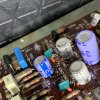
P900 Phono Board C924/C925 10uf-25v
Board polarity markings are reversed

Everything else was good. I documented all resistors, transistors, diodes, e-caps. Only small difference in early models was the helper filter cap which later changed to a slightly larger single main filter.
Mike
P900 Phono Board C909/C910 100uf-6.3v
Board polarity markings are reversed
P900 Phono Board C924/C925 10uf-25v
Board polarity markings are reversed
Everything else was good. I documented all resistors, transistors, diodes, e-caps. Only small difference in early models was the helper filter cap which later changed to a slightly larger single main filter.
Mike

Dunno if this is in there...In the 2252B SM from hifi E. page 19 and 20 for P700 board...Q715/716 are listed as 2SD945. They aint, parts list has em as 2SC945 and you will yank a 2SC945, but the print is wrong.

Marantz 2500 SM error
All over the service manual, it has the bias trim pot labeled R716.
Its R761 on the boards. The one in the middle of the board.
All over the service manual, it has the bias trim pot labeled R716.
Its R761 on the boards. The one in the middle of the board.

rustyhusky
Member
2325 - Just got burned on this one while doing a rebuild of the P200 FM IF board. Parts list in service manual calls out C244 and C245 as 100uf, 10V electrolytics, which is incorrect. C244 and C245 are actually 10uf, 16V electrolytics as installed and also as shown on the schematic.

klamsoss
Be willing to fail and try again.
Marantz master catrafter helped me figure out there is an error in the 2330B schematics.
For the speaker switch, fm muting, miltipath, mpx noise filter board (PU01 in the manual) CU03 doesn't exist, thought it is silk screened on the board.
A cap of the same value (10uF 16V) is actually floated between JU14 and JU18
For the speaker switch, fm muting, miltipath, mpx noise filter board (PU01 in the manual) CU03 doesn't exist, thought it is silk screened on the board.
A cap of the same value (10uF 16V) is actually floated between JU14 and JU18
Attachments


P800 variation on the 1060
I'm currently working on two virgin Model 1060's: S/N 28420, datestamp 49.1.23 (January 23, 1974), and S/N 43259J4, datestamp 50.7.28 (July 28, 1975). Both units have the second variation of the P800 circuit board (YD2828005-0), which is the version that uses J808 as a 7.27vac tie point for the power indicator lamp circuit, as documented by @gch53 here: Marantz Service Manual error thread
What I've also found in both of my units is that resistors R803 and R804 deviate from the S/M parts list and schematic as follows:
- R803 listed as 33K 10%, but installed is 27K Ohm 5% (red-violet-orange-gold)
- R804 listed as 470 10%, but installed is 100 Ohm 5% (brown-black-brown-gold)
Since I do not have an example of the first version of the PCB (YD2828004) to compare with, I can only surmise that this was part of the design revision rather than a S/M error per se.
(Also: Just found that further evidence of this for R804 was documented once before, by @Yankee Dog here: Under the Hood of a 1060 ) https://audiokarma.org/forums/index.php?threads/under-the-hood-of-a-1060.238272/
Just hoping to contribute in a small way to this invaluable thread, since I've learned so much here!
Cheers,
Steve
I'm currently working on two virgin Model 1060's: S/N 28420, datestamp 49.1.23 (January 23, 1974), and S/N 43259J4, datestamp 50.7.28 (July 28, 1975). Both units have the second variation of the P800 circuit board (YD2828005-0), which is the version that uses J808 as a 7.27vac tie point for the power indicator lamp circuit, as documented by @gch53 here: Marantz Service Manual error thread
What I've also found in both of my units is that resistors R803 and R804 deviate from the S/M parts list and schematic as follows:
- R803 listed as 33K 10%, but installed is 27K Ohm 5% (red-violet-orange-gold)
- R804 listed as 470 10%, but installed is 100 Ohm 5% (brown-black-brown-gold)
Since I do not have an example of the first version of the PCB (YD2828004) to compare with, I can only surmise that this was part of the design revision rather than a S/M error per se.
(Also: Just found that further evidence of this for R804 was documented once before, by @Yankee Dog here: Under the Hood of a 1060 ) https://audiokarma.org/forums/index.php?threads/under-the-hood-of-a-1060.238272/
Just hoping to contribute in a small way to this invaluable thread, since I've learned so much here!
Cheers,
Steve

Sergimm
Active Member
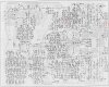
I believe I found another error while restoring a 1050 (valid also for 1072, as they share SM). In the schematic there is a diode with the same name as a transistor: Q710. See the attached image of the schematic.
I am not good enough at electronics to find out which one is the actual reference of the wrongly named diode, so I attach the PCB diagram with the real Q710 transistor and the Q706 transistor (which is next to the diode in the schematic) marked so that somebody more skilled at this than me can spot what should that diode actually be called.
I'm a complete newbie, so it could also be that I am wrong in all this!
Cheers!
I am not good enough at electronics to find out which one is the actual reference of the wrongly named diode, so I attach the PCB diagram with the real Q710 transistor and the Q706 transistor (which is next to the diode in the schematic) marked so that somebody more skilled at this than me can spot what should that diode actually be called.
I'm a complete newbie, so it could also be that I am wrong in all this!
Cheers!
Attachments

Last edited:

That applies to the 2226 as well.The 2238 (not B) manual identifies Q804 as the 2SC945 transistor and Q806 as the SIB01-02 diode, but I believe they are switched around on the board. The 2252 (not B) has the same issue.

2330B P800 errors: Parts list cap values diverge from schematic for C817, C818. Please confirm polarity for C817 and cap value, please confirm cap value for C818This is a compilation of errors in Marantz service manuals. These corrections will likely save you from smoking your receiver. Remember to use some good mini grabber leads when you're adjusting bias, I've read way too many horror stories of slipping probes.
Big thanks to Tom (catrafter) for contributing most of these.
2220B Idle current adjust:
SM says measure J712 - 718 for one channel, 713 to 719 for the other. WRONG! Do this instead: Measure bias at J714 to 716 and adjust R733 for 20mVDC on that channel. Then measure J715 to 717 and adjust R734 for 20mV on the other channel.
2220B Cap listing:
Service manual lists CE21 & CE22 as 33 uF/50v. Should be 3.3 uf/50v.
CE23 & CE24 listed as standard 1.0 uF/50V. Use non polar caps here.
C709 and C710 should be 47uf 50V, not the listed 500V.
2230 Voltage adjustment:
Manual says measure J08 to Ground. Should be J808.
2265B Parts list error:
SM shows 1000uF/55V for C003/C004 filter capacitors. Value should be 10000uF/55V.
2270 SN<3901 Idle current or bias adjust:
Meter set to read DC mV, connect from J753 to J754, set R763 for 5mV
2270 SN>3900 Idle current or bias adjust:
Meter set to read DC mV, connect from J754 to J760, set R763 for 10mV
2275 Idle current or bias adjust:
SM says measure 707-708, adjust R742 for 10mV. Do this instead: Meter set to read DC mV, connect from J703 to J704, set R742 for 10mV
2325 Silk screen is wrong on PH01 board:
Positive side of CH13 goes toward the center of the board.
1060 diode (early models):
http://www.audiokarma.org/forums/showthread.php?t=439676
1070 DC Offset adjust:
SM says R724, change to J724.
1070 Cap List error:
SM lists CE05/06 as 47uF/35V. Amp actually uses 4.7uF/25V, reflected on schematics as well.
2230, 2245, 2270 AM tuner:
C183 silk screen is backwards. The + side of the cap goes to chassis ground.
C181 has no polarity silk screen. The + side goes toward the edge of the board.
2330B Schematic Error - http://www.audiokarma.org/forums/showpost.php?p=5022087&postcount=23
If you know any other errors in Marantz SMs, please post them.

Stereodiver
Well-Known Member
I hope I'm not duplicating anything that's already been said.
2252 (non b)
P700 main amp board. R735, 736, 737, 738, 270ohm, not 330ohm. R739, 740, 741, 742, 743, 744, 220ohm, not 270ohm. R747, 748, 2.4k, not 5.1k. R749, 750, 2.7k, not 5.6k. R751, 752, 24k, not 22k. R776, 470, 1w, not 330ohm.
P800 power supply board. C803, 470uf @ 63v, not 50v. C809, 1000uf @ 16v, not 10v.
PE01 tone board. RE35, 36, 200k, not 330k. CE21, 22, 3.3uf @ 50v, not 33uf @ 50v
This is how I learned that resistor color codes are your FRIEND!
Mark
2252 (non b)
P700 main amp board. R735, 736, 737, 738, 270ohm, not 330ohm. R739, 740, 741, 742, 743, 744, 220ohm, not 270ohm. R747, 748, 2.4k, not 5.1k. R749, 750, 2.7k, not 5.6k. R751, 752, 24k, not 22k. R776, 470, 1w, not 330ohm.
P800 power supply board. C803, 470uf @ 63v, not 50v. C809, 1000uf @ 16v, not 10v.
PE01 tone board. RE35, 36, 200k, not 330k. CE21, 22, 3.3uf @ 50v, not 33uf @ 50v
This is how I learned that resistor color codes are your FRIEND!
Mark


catrafter
Marantz Specialist
The polarity of C702 should be irrelevant in a properly operating amp.C702 cap polarity on Hi-Res 2275 schematic is reversed.
"+" sign should be on input gnd rail
The voltage at that point represents the amount of offset correction required (which ideally should be very close to zero, within a few mV, plus or minus) to balance the output at zero volts. Electrolytic capacitors are polarized, but will happily operate reverse polarized at very small voltage levels, IMHO.
Tom
As you had found out, my 2265B's P700 board was installed same valued resisters.Descrepancies with the Marantz 2265B service manual I ran across while doing a rebuild.....
- P700 Main Amp Circuit Board: Siamesed transistors Q756/Q758 incorrectly identified as Q766/Q760 on right channel circuit board silk screen
- P700 Main Amp Circuit Board: Capacitors C718/C768 & C719/C769 shown as 0.1 uF in manual but replaced by jumpers from the factory.
- P700 Main Amp Circuit Board: The following component values shown in the service manual are different from what was installed from the factory:
· R729/R779 & R733/R783, 200 ohm called out, 300 ohm factory installed
· R730/R780 & R734/R784, 160 ohm called out, 300 ohm factory installed
· R731/R781 & R735/R785, 300 ohm called out, 820 ohm factory installed
· R732/R782 & R736/R786, 2.4K ohm called out, 1.6K ohm factory installed
· R737/R787, 36K ohm called out, 43K ohm factory installed
Do you have any idea whether it's OK when the resisters are installed as the service manual's value?
2226 Tuner Board
SM says R210 is 27K ohms, my board has 10K ohm resistor that looks original.
SM says R210 is 27K ohms, my board has 10K ohm resistor that looks original.
Really? There were many modification on the manufacture. Why I had not enough time to test, I installed the resisters as not SM but manufacted values.2226 Tuner Board
SM says R210 is 27K ohms, my board has 10K ohm resistor that looks original.