• The move to the new server is done. There are some software and database maintenance updates in process. This has us passing the hat around to help out. We appreciate any donations. Seriously, even a dollar helps. The payment page may be found here - https://www.audiokarma.org/support.html

Marantz Service Manual error thread

Really? There were many modification on the manufacture. Why I had not enough time to test, I installed the resisters as not SM but manufacted values.

Coming more and more to the conclusion that the scrub engineers were put in charge of the service manuals, or maybe just temps. Marantz S.M.s are actually among the best.

When you find anomalies like the resistor you can't be sure whether the SM is right, especially if the part doesn't look like it was replaced.
 
Coming more and more to the conclusion that the scrub engineers were put in charge of the service manuals, or maybe just temps. Marantz S.M.s are actually among the best.

When you find anomalies like the resistor you can't be sure whether the SM is right, especially if the part doesn't look like it was replaced.
Thank you for your comment. If I have a chance to test or to repair, I'll try to install as SM specificated.
 
Marantz 2010:
R156: SM shows 4K7 value and factory on-board is 47K. Effects stereo light and activation sensitivity.
R159: SM Shows 12K value and factory on-board is 18K. Effects stereo light and activation sensitivity.

Whether this was a last minute bulletin is unknown, but following the schematic corrected a stubborn stereo light issue for me.
Technically, this isn't a SM error, but I wasn't sure where to post it.
 
Model 28
Service manual error.
Resistor 437 marked as a 3.9 ohm should be 3.9K ohm.
2250 P700 SM parts list shows R720 300K Ω 1/4W. Schematic of P700 above foil side diagram shows 200Ω. I'm not sure which is correct.
 
Hi, one more found today : Marantz PM-710 DC schematic says R743,744,745,746 are 10 Ohm where they are in fact 390 Ohm. All fuse resistors, drifting.
 
2252 (non B)

DOC: 2252 service manual
Issue: P700 Main Amp Schematic has resistor and cap designation errors These errors are not on the silkscreen diagram.

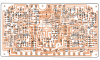
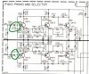
here is a marked up schematic for the protection circuit along with the silkscreen print.

2252 protect errors.png

2252 protect board drawing correct.png
 
This is a compilation of errors in Marantz service manuals. These corrections will likely save you from smoking your receiver. Remember to use some good mini grabber leads when you're adjusting bias, I've read way too many horror stories of slipping probes.

Big thanks to Tom (catrafter) for contributing most of these.

2220B Idle current adjust:
SM says measure J712 - 718 for one channel, 713 to 719 for the other. WRONG! Do this instead: Measure bias at J714 to 716 and adjust R733 for 20mVDC on that channel. Then measure J715 to 717 and adjust R734 for 20mV on the other channel.

Wish i had seen this thread before : i followed the service manual for idle adjustment and R757 litterally caught fire before my eyes !
I should have suspected something was wrong when i turned on the amp and my multimeter started beeping but i couldn't figure out why it was and by the time i decided to turn off the amp, resistor was gone in smoke.
Pretty crazy to think they'd make such a mistake. I'm by no means a technician but i'm trying to learn more about those units.
Do you think there might be other issues that caused this or the wrong pins are to blame ?
Anyway, i Hope Nothing more was fried in the process.
 
Didn't see this here:

Marantz 1152DC parts list C715 & C716 as 22uF 100V when the factory installed parts are 35V just like in the schematic.

parts list wrong (100V), schematic correct (35V)


-----

Additional error in 1152DC manual:

Schematic has incorrect voltage on the collector of Q854. -36V should be -56V
 
Last edited:
The Marantz 2245 Service Manual posted in the AKDatabase is missing page 27 of the parts list. I aim to remedy this, but I am at the mercy of the Administrator for database uploads. About 3 months ago ( maybe longer) I submitted a high quality color copy of the original Handbook of Instructions for the model 3200 pre-amp and as of now the Administrator still has not uploaded it. I will submit the missing page for the 2245 Service Manual today.
 
2220B contains Dolby FM board that is not mentioned in service manual. See 2230B service manual for details
 
Marantz 2245 Service Manual schematic & parts list for Power Amp Board both show Bias Pot R763 as 1K Ohms. Actual value installed is 2.2K, same as R762
 
Last edited:
Marantz 2265B

C409 & C410 Service Manual parts list shows 100uF @10v, schematic shows 33uF @10v, actual original caps install in board 33uF @10v. I'm going with schematic and actual.
 
2226 P400 Phono and Selector Variation

Didn't see this noted before.

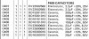
C401 and C402 (2.2uF/25V, Blue tantalum) are correct in the parts list. C401 is shown incorrectly as 22uF/25V on schematic. C402 is shown but no values are given.
2226 phono parts 1.jpg

2226 phono 1.jpg
 
Service Manual of Marantz PM310.

I compared the service manual with a 1980 PM310. Note 1981 PM310 has slight changes on the board. The 1981 version is not discussed further here. However, the 1980 version is discussed here.

There are a number of errors in it and
and some improvements and clarification are needed:

C416 may have a deviation of +80- -20%.
C705 and C706 are on the main board 100uF and not 1000uF. That's one zero too many.
C703 may have a deviation of 10%.
CN01 is on the main board 10 volts and not 6.3 volts as in the manual
C813 does not exist (not in the inventory nor on the main board), however C813 is drawn on the drawing as an electrolytic capacitor.
C809 does not exist, (not in inventory and not on main board), however C809 is drawn on the drawing as a film/ceramic capacitor.
C729 and C730 are not in the book. But on the main board. These are ceramic 181. I have yet to find the corresponding uF value.
Q811 does not exist in the book. but on the main board. This is a diode DS135D.

Design differences between 1980 (0XE...) and 1981 (1YE...) version

The 1981 version has:
- "Designed in USA" has been removed from the nameplate on the newer ones.
-Transitions Q710 and Q709 are now attached to the heatsink.
- Motherboard has slight changes in the copper tracks. some transistors have been relocated.
- Motherboard has been given a different color green (light green instead of dark green)
- Rough instead of smooth coating of the housing (similar to SR1100).
- Case color is darker and closer to SR1100. It is less metallic-like due to the rough coating. it doesn't look like Champagne Gold anymore.
- Other brand capacitors. (ELNA vs Nippon Chemicon).
- Design of the power supply has been slightly changed. (type number remains the same)
 
Last edited:
And I forgot to mention this. Where in the service manual of Marantz PM310 you read 82.7 volts, there should be 32.7V.
Because the preceding capacitor is one of 35 volts.
 
Maybe there are two types of 2230B. The service manual for both the 2220B and 2230B are wrong for the 2230B I'm looking at.

It looks like they want to measure across the emitter resistors to do the bias setting. The schematic shows J712 and J718 connecting across one side and J713 and J719 connecting across the other side. The board isn't set up that way.

J714 and J716 connect across one set of emitters and J715 and J717 across the other set.

SO.

Connect J714(+) and J716(-) and adjust R733 for 20mV.
Connect J723(+) and J722(-) and adjust R711 for 0mV.
Repeat.
Connect J715(+) and J717(-) and adjust R734 for 20mV.
Connect J724(+) and J722(-) and adjust R712 for 0mV.
Repeat.

These revised test points also apply to the 2225
 
This is a compilation of errors in Marantz service manuals. These corrections will likely save you from smoking your receiver. Remember to use some good mini grabber leads when you're adjusting bias, I've read way too many horror stories of slipping probes.

Big thanks to Tom (catrafter) for contributing most of these.

2220B Idle current adjust:
SM says measure J712 - 718 for one channel, 713 to 719 for the other. WRONG! Do this instead: Measure bias at J714 to 716 and adjust R733 for 20mVDC on that channel. Then measure J715 to 717 and adjust R734 for 20mV on the other channel.

2220B Cap listing:
Service manual lists CE21 & CE22 as 33 uF/50v. Should be 3.3 uf/50v.
CE23 & CE24 listed as standard 1.0 uF/50V. Use non polar caps here.
C709 and C710 should be 47uf 50V, not the listed 500V.

2230 Voltage adjustment:
Manual says measure J08 to Ground. Should be J808.

2265B Parts list error:
SM shows 1000uF/55V for C003/C004 filter capacitors. Value should be 10000uF/55V.

2270 SN<3901 Idle current or bias adjust:
Meter set to read DC mV, connect from J753 to J754, set R763 for 5mV

2270 SN>3900 Idle current or bias adjust:
Meter set to read DC mV, connect from J754 to J760, set R763 for 10mV

2275 Idle current or bias adjust:
SM says measure 707-708, adjust R742 for 10mV. Do this instead: Meter set to read DC mV, connect from J703 to J704, set R742 for 10mV

2325 Silk screen is wrong on PH01 board:
Positive side of CH13 goes toward the center of the board.

1060 diode (early models):
http://www.audiokarma.org/forums/showthread.php?t=439676

1070 DC Offset adjust:
SM says R724, change to J724.

1070 Cap List error:
SM lists CE05/06 as 47uF/35V. Amp actually uses 4.7uF/25V, reflected on schematics as well.

2230, 2245, 2270 AM tuner:
C183 silk screen is backwards. The + side of the cap goes to chassis ground.
C181 has no polarity silk screen. The + side goes toward the edge of the board.

2330B Schematic Error - http://www.audiokarma.org/forums/showpost.php?p=5022087&postcount=23

If you know any other errors in Marantz SMs, please post them.[/QUO

 
Back
Top Bottom