• The move to the new server is done. There are some software and database maintenance updates in process. This has us passing the hat around to help out. We appreciate any donations. Seriously, even a dollar helps. The payment page may be found here - https://www.audiokarma.org/support.html

Mark's 2235B restoration

...with the Pioneer recaps I've done, Markthefixer uses low leakage caps in the audio path and general purpose caps elsewhere. I think I read that's where Leestereo and MTF differ. One usually opts for low leakage current and Leestereo uses low esr...

Actually, in the audio/signal path, my preference is to use film capacitors whenever possible, i.e., for capacitors that are ≤4.7µF. For larger values I will typically install Nichicon ES bi-polar types. This approach is largely derived from the research work of Cyril Bateman examining the impact of capacitors on sound quality: https://linearaudio.nl/cyril-batemans-capacitor-sound-articles. He tested electrolytic capacitors extensively and demonstrated that in AC coupling, bipolar electrolytic capacitors have the lowest distortion/noise of all the electrolytic types (even the presence of a polarizing voltage) and that film capacitors are generally lower distortion/noise than electrolytic capacitors of any type.
 
Actually, in the audio/signal path, my preference is to use film capacitors whenever possible, i.e., for capacitors that are ≤4.7µF. For larger values I will typically install Nichicon ES bi-polar types. This approach is largely derived from the research work of Cyril Bateman examining the impact of capacitors on sound quality: https://linearaudio.nl/cyril-batemans-capacitor-sound-articles. He tested electrolytic capacitors extensively and demonstrated that in AC coupling, bipolar electrolytic capacitors have the lowest distortion/noise of all the electrolytic types (even the presence of a polarizing voltage) and that film capacitors are generally lower distortion/noise than electrolytic capacitors of any type.
I apologize for any misunderstanding. I was trying to recall a thread I had come across at some point in time. I vaguely remember someone discussing a difference between caps you normally choose vs markthefixer. And whoever was doing the writing might have been completely wrong. Could I be thinking about caps that are not in the signal path? You did send me that link once before when I was asking about the recap list I had for my SX-850. I believe at the time I was asking about using film capacitors. I am quite certain I have read a post where mtf claimed the audio caps are snake oil and seemed to have some home testing to back up his argument. Although without links to back up my comments it's all heresay. Unfortunately, I don't save most of the threads I read on here.
 
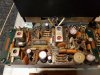
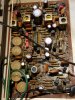
Today's project was to get the MPX board recapped. The owner of this stereo said it was in a flood at one point. He was astonished that it still works.
 

Attachments

  • 20200708_202845.jpg
    20200708_202845.jpg
    171.9 KB · Views: 34
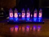
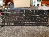
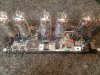
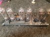
Took a day off from the stereo repair while waiting for parts. I have been wanting a clock down in my workshop for a while now. I ordered a nixie tube clock DIY kit. After waiting about a month and a half it arrived from Ukraine. I have to say it was a fun little project. I've never had to solder anything as small as some of the components on this thing. And most importantly it actually works! Hahaha
 

Attachments

  • 20200710_182227.jpg
    20200710_182227.jpg
    97 KB · Views: 35
  • 20200710_181834.jpg
    20200710_181834.jpg
    176.1 KB · Views: 33
  • 20200710_180019.jpg
    20200710_180019.jpg
    193.4 KB · Views: 33
  • 20200710_175954.jpg
    20200710_175954.jpg
    194.7 KB · Views: 32
As I have already stated I have been reading @Leestereo's 2235B restoration thread that can found HERE. In his rebuild he noted how heat from the 150 ohm 5 watt dropping resistor had deformed two capacitors due to the heat it produces. I had noticed the same issue on this power supply board. Mr. Leestereo was kind enough to share his power supply rebuild list so I recapped my power supply/relay board the same way he did in his thread. I also replaced the DS131B's with MUR1620CTG's as recommended by patfront in the same thread.

EDIT: Since I already have some here I went ahead and replaced the 2SC945's with KSC2383YTA's on the same board.
 

Attachments

  • 20200711_204239.jpg
    20200711_204239.jpg
    166.6 KB · Views: 32
Last edited:
Also today I finished recapping the FM IF amp board. Didn't take a picture due to the fact that there really isn't much to see. It was only 5 or 6 caps I believe. The tuner was out of alignment before starting this project. The fm tuning meter is slightly right of center when in stereo mode. I want to see how to re-center it if it's not too much trouble. Also the dial pointer seems to be pretty evenly left of the station it should be on across the whole scale. I have been thinking I might just move the dial pointer manually. The fm signal strength seems to be improved after recapping the board. If anyone can tell me how to re-center the tuning meter that would be amazing.

EDIT: THIS thread seems to address the issue I'm having with the meter. Now I need the tool to do it.
 
Last edited:
Bought a set of tuner alignment tools. Right now I'll only probably end up using one to get the meter centered. I've read up about how performing tuner alignments is difficult and requires a great deal of skill. And even then not many people are great at doing them. I'd really like to learn more about that. Until then I guess it's physically moving the pointer until it's on the correct station. :(
 
My $30 dmm just up and died today. It was inexpensive but seemed to work well for about a year. I think I'm ready to invest in something a little better. Any suggestions? Fluke? Until I figure out what I'm going to replace it with I went the CHEAP harbor freight route. Hopefully this cheap one isn't completely inaccurate. Anyways, after buying another dmm, doing an oil change, and trimming the hedges I had some time to get the AM board recapped. Doubt the AM radio is going to see much action but it's done nonetheless. I will say that using a kit and having everything bagged separately is very convenient. You can fly through it!
 

Attachments

  • 20200712_182844.jpg
    20200712_182844.jpg
    128.5 KB · Views: 14
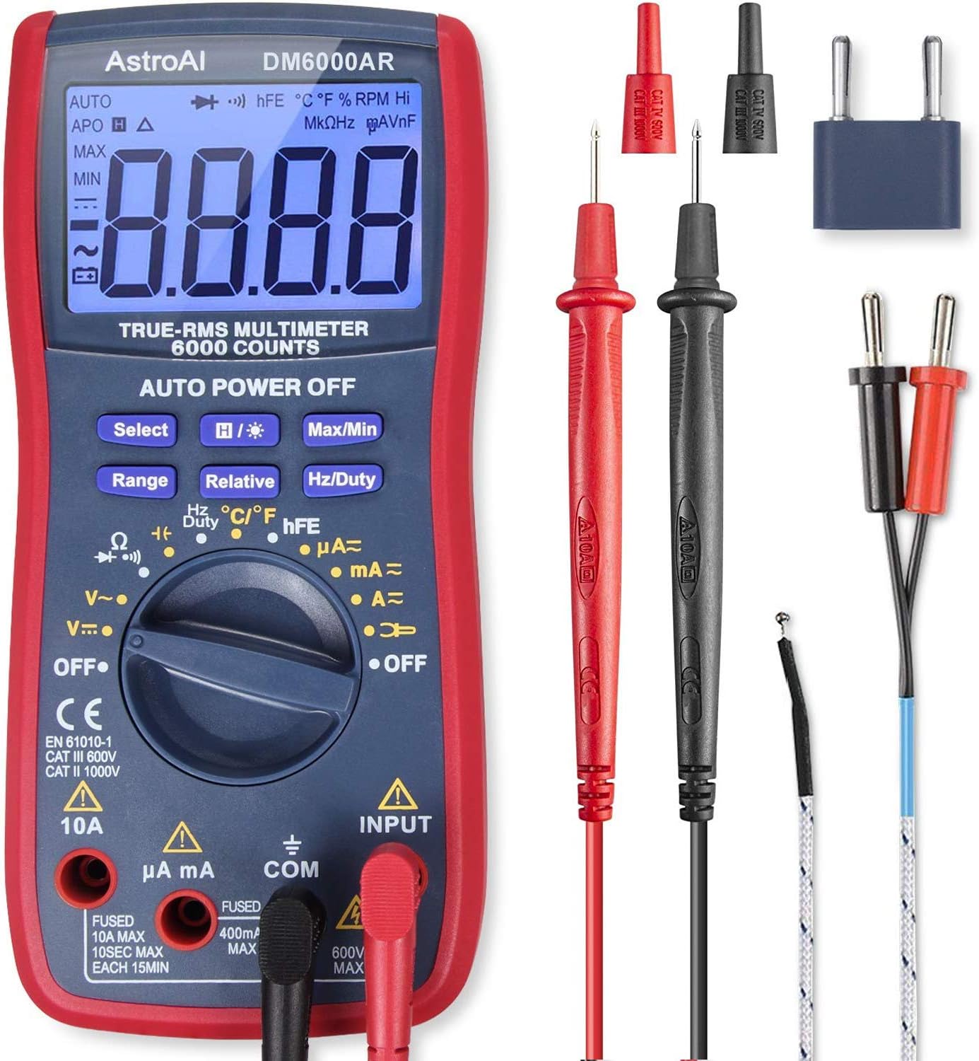
I recently got this one for $35 - works great and has a lot of features:
https://www.amazon.com/gp/product/B071JL6LLL/ref=ppx_yo_dt_b_asin_title_o06_s01
718XzreO85L._AC_SL1500_.jpg


Upgraded probe and clip kit:
https://www.amazon.com/gp/product/B06XYNF47M/ref=ppx_yo_dt_b_asin_title_o06_s01?ie=UTF8

Case for it:
https://www.amazon.com/gp/product/B07PMJKMXR/ref=ppx_yo_dt_b_asin_title_o03_s00?ie=UTF8

Can't go wrong with a Fluke, but this inexpensive setup is great.
 
Most any multi meter will work in a pinch, however Fluke multimeters are very durable and reliable. I own three Flukes, two were bought at flea markets for pennies where the seller though they were broken.
 
I recently got this one for $35 - works great and has a lot of features:
https://www.amazon.com/gp/product/B071JL6LLL/ref=ppx_yo_dt_b_asin_title_o06_s01
718XzreO85L._AC_SL1500_.jpg


Upgraded probe and clip kit:
https://www.amazon.com/gp/product/B06XYNF47M/ref=ppx_yo_dt_b_asin_title_o06_s01?ie=UTF8

Case for it:
https://www.amazon.com/gp/product/B07PMJKMXR/ref=ppx_yo_dt_b_asin_title_o03_s00?ie=UTF8

Can't go wrong with a Fluke, but this inexpensive setup is great.
That looks pretty decent. Similar to what I had. Although not the same one. I went to turn mine on yesterday and it was beeping and the screen was flashing. It was doing all sorts of crazy things. Worked fine the day before.
 
Well, I reached out to the manufacturer who made my multimeter. Sent a bunch of photos of what it's doing. They said they're going to send me a replacement. So I can hold off on the Fluke for now. I started looking at those and didn't realize that some can get up to around $400!
 
I use a Fluke 115. It has all the features I need with Fluke quality for about $150.
Thank you, that is the information I was looking for at a price point I'm comfortable with. I believe some of the more expensive Flukes are tailored toward professional HVAC installers.
 
I have finished recapping the main amplifier. While working on the amp I pulled the output transistors. I applied new Thermalcote to them along with installing new mica insulators. As far as what I had planned for the amp I would be finished with one exception. This recap kit came with (4) 1N4148 diodes. There's a note that says replace H717 and H718 each with 2 diodes in series. I get the idea is to solder the two diodes together. However, H717 is a MV-13 varistor and H718 is a IS2472 diode. Is it safe to assume we actually want to replace H718 and H719? Can anyone elaborate on the reasoning for doing this? Specifically because there are several IS2472 diodes on the amplifier.
 

Attachments

  • 20200714_191956.jpg
    20200714_191956.jpg
    92.8 KB · Views: 31
  • 20200715_164801.jpg
    20200715_164801.jpg
    158 KB · Views: 34
Last edited:
One bit of advice I should have taken was to wait to install the main filter capacitors. They were definitely in the way while working on the amp. I was able to make it work but it was a tight squeeze. If my soldering iron was bigger in diameter I don't think it would have fit behind the amp board and the heatsink. In hindsight removing one of the trimmers would have made life easier.
 
Last edited:
Back
Top Bottom