

You are using an out of date browser. It may not display this or other websites correctly.
You should upgrade or use an alternative browser.
You should upgrade or use an alternative browser.
Mark's 2235B restoration
- Thread starter mstewart
- Start date
-
- Tags
- marantz 2235b

mstewart
Active Member
Well I stumbled across the answer to my question in an unlikely way with no explanation. It appears that the (2) IN4148 diodes are infact meant to replace the MV-13 varistors. Glad I didn't go with what I was originally thinking! I decided since the amp appears to working fine it was safer to not do something I didn't feel comfortable about.
mstewart
Active Member
Today I received the replacement dmm. Wasn't expecting to get it this fast. Here's a question for anyone who could chime in. While looking at different dmms I found that the one I have doesn't have true rms. I have read several explanations about the difference between true rms and rms. But what I'm not clear about is whether that function would get used working on stereos since we're mostly dealing with dc?
mstewart
Active Member
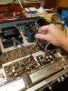
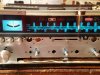
I also received the tuner alignment set I bought. Centering the tuning meter was quick and easy when following the instructions in the link I posted. I also ended up moving the dial pointer so it's on the correct station and changed the dial pointer light since I had not done that yet. I also adjusted the regulator voltage, dc offset, and bias. I am planning on posting instructions how to adjust everything in case it will help someone else.
Attachments

If dealing with only DC then no worries with RMS meters. Putting it simply, the true RMS instruments are more accurate than RMS when measuring AC current. The accuracy of true RMS measurements is usually not nearly as good at averaging DC measurements as RMS meters are.While looking at different dmms I found that the one I have doesn't have true rms. I have read several explanations about the difference between true rms and rms. But what I'm not clear about is whether that function would get used working on stereos since we're mostly dealing with dc?
Last edited:

Steven Tate
CEO Flat Forehead Soc.
Sounds like you are making great progress. Well done!
mstewart
Active Member
That's good to know!If dealing with only DC then no worries with RMS meters. Putting it simply, the true RMS instruments are more accurate than RMS when measuring AC current. The accuracy of true RMS measurements is usually not nearly as good at averaging DC measurements as RMS meters are.
mstewart
Active Member
Thanks! There is not much left to do really. My plan was to let it play for a while and then recheck everything. I also need to hook up my record player to make sure everything is sounding good.Sounds like you are making great progress. Well done!
mstewart
Active Member
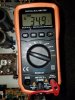
How to set the Automatic Voltage Regulator:
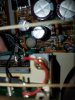
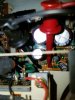
The service manual for this stereo instructs the adjustment is to be performed under no signal condition. I put the stereo in aux, with the volume turned down, and no speakers connected while performing all of the adjustements. Next you are to connect a VTVM or DMM, on the power supply board P800, with the positive probe on pin J804 and the negative on pin J805. Then you want to turn R806 until your reading is 35vdc. I used mini grabbers to hold my leads in place while setting the correct voltage.
The service manual for this stereo instructs the adjustment is to be performed under no signal condition. I put the stereo in aux, with the volume turned down, and no speakers connected while performing all of the adjustements. Next you are to connect a VTVM or DMM, on the power supply board P800, with the positive probe on pin J804 and the negative on pin J805. Then you want to turn R806 until your reading is 35vdc. I used mini grabbers to hold my leads in place while setting the correct voltage.
Attachments
Last edited:
mstewart
Active Member
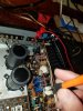
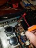
How to set the Main Amplifier DC Offset:
To begin, the service manual states that the alignment is to be performed with no load connected to the SPEAKER terminals. It instructs you to connect a DC voltmeter or DMM with a .5 or 1v range. I believe most if not all dmm's will have a tighter range than that. Next it instructs you to connect your probes between the speaker terminals and adjust the trimming resistor R713 until your meter reads 0v. It then goes on to say that you want to repeat the procedure for the other channel. This is a little vague but easy to figure out.
What it does not say is that you want to connect to the left speaker terminals while adjusting R713. And then the right speaker terminals while adjusting R714. It does not matter which is positive and which is negative, really, because the end goal is to get a reading of 0v. What would happen if you switch the probes and connect them backwards is that you will get a negative reading when it's supposed to be positive.
To begin, the service manual states that the alignment is to be performed with no load connected to the SPEAKER terminals. It instructs you to connect a DC voltmeter or DMM with a .5 or 1v range. I believe most if not all dmm's will have a tighter range than that. Next it instructs you to connect your probes between the speaker terminals and adjust the trimming resistor R713 until your meter reads 0v. It then goes on to say that you want to repeat the procedure for the other channel. This is a little vague but easy to figure out.
What it does not say is that you want to connect to the left speaker terminals while adjusting R713. And then the right speaker terminals while adjusting R714. It does not matter which is positive and which is negative, really, because the end goal is to get a reading of 0v. What would happen if you switch the probes and connect them backwards is that you will get a negative reading when it's supposed to be positive.
Attachments

mstewart
Active Member
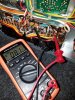
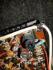
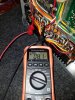
How to set the Idle Current or Bias:
Like the DC offset this adjustment is to be performed with no load on the speaker terminals. The service manual instructs you to connect a VTVM or DMM, between pins J713 and J717. Then adjust the trimming resistor R766 until you get a reading of 8mV. Next, repeat the procedure for the other channel.
I tried to connect my probes both ways that are possible. One way will give you only negative readings. If you turn the trimmer all the way in one direction it only goes to zero. So you can't accidentally go past and end up setting the the bias voltage at -8mV. However, to get a proper readout on your dmm, you want your positive probe on J713 and the negative on J717.
You can see that both channels of the amplifier are mirror images of each other. So to do the other channel you want to connect the probes to J714 and J718. Then adjust trimming resistor R767.
Finally, after your idle current has been set, the service manual states that you are to reset the DC Offset.
Like the DC offset this adjustment is to be performed with no load on the speaker terminals. The service manual instructs you to connect a VTVM or DMM, between pins J713 and J717. Then adjust the trimming resistor R766 until you get a reading of 8mV. Next, repeat the procedure for the other channel.
I tried to connect my probes both ways that are possible. One way will give you only negative readings. If you turn the trimmer all the way in one direction it only goes to zero. So you can't accidentally go past and end up setting the the bias voltage at -8mV. However, to get a proper readout on your dmm, you want your positive probe on J713 and the negative on J717.
You can see that both channels of the amplifier are mirror images of each other. So to do the other channel you want to connect the probes to J714 and J718. Then adjust trimming resistor R767.
Finally, after your idle current has been set, the service manual states that you are to reset the DC Offset.
Attachments


lshj2015
Active Member
I also received the tuner alignment set I bought. Centering the tuning meter was quick and easy when following the instructions in the link I posted. I also ended up moving the dial pointer so it's on the correct station and changed the dial pointer light since I had not done that yet. I also adjusted the regulator voltage, dc offset, and bias. I am planning on posting instructions how to adjust everything in case it will help someone else.
Thank you for your post. I have the same problem with my tuning meter. I read the link you posted and adjusted my tuning meter, use a wood stick and it works great. Otherwise, I might just use a metal tool and cause problem.
https://audiokarma.org/forums/index.php?threads/marantz-2275-fix-and-rebuild.921136/page-2
mstewart
Active Member
That's great! I'm glad it helped.Thank you for your post. I have the same problem with my tuning meter. I read the link you posted and adjusted my tuning meter, use a wood stick and it works great. Otherwise, I might just use a metal tool and cause problem.
https://audiokarma.org/forums/index.php?threads/marantz-2275-fix-and-rebuild.921136/page-2
mstewart
Active Member
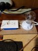
The tools I have been using are a Tilswall soldering iron, Chem-Wik desoldering wick, Kester rf741 flux, eutetic solder, and my dim bulb tester. I really like this soldering iron compared to my super cheap old one. I think it was only around $40 online. It gets to temperature in about 10 seconds and seems to stay there well. After every board I worked on, the stereo would be powered on while plugged into the dim bulb tester. I have a low budget desoldering iron/pump that wasn't used at all.
Attachments

Last edited:
Steven Tate
CEO Flat Forehead Soc.
A good desoldering gun makes this work so much easier. I did a short video in the Hakko FR300 a couple of years ago. There is now an FR301, and I think a second generation of that. I wouldn’t work without one.
https://audiokarma.org/forums/index.php?threads/use-of-hakko-fr300-desoldering-gun-video.741463/
https://audiokarma.org/forums/index.php?threads/use-of-hakko-fr300-desoldering-gun-video.741463/
mstewart
Active Member
I'll watch that video. Thank you for sending the link. I definitely want a good desoldering gun. I'll admit that it takes much longer without one. The desoldering tool I have seems to work but it leaves solder on the circuit board. So then I have to follow up with wick. The extra step makes it take even longer.A good desoldering gun makes this work so much easier. I did a short video in the Hakko FR300 a couple of years ago. There is now an FR301, and I think a second generation of that. I wouldn’t work without one.
https://audiokarma.org/forums/index.php?threads/use-of-hakko-fr300-desoldering-gun-video.741463/

lshj2015
Active Member
She went home today. The owner was very happy with how it turned out. That was nice. One last pic before it left my bench.
View attachment 1930595
That's a nice looking receiver. I think it looks prettier than the 2245 that I recently bought.
mstewart
Active Member
After watching @Steven Tate's video I am a believer. Just pulled the trigger on a Hakko FR-301. I had been on the fence for a while. Now is a good time because I've got more stereos to recap.
lshj2015
Active Member
After watching @Steven Tate's video I am a believer. Just pulled the trigger on a Hakko FR-301. I had been on the fence for a while. Now is a good time because I've got more stereos to recap.
I bought one based on Randy's recommendation when I bought the rebuild kit from him. Well worth it, it saved me a lot of time to get the job done.