• The move to the new server is done. There are some software and database maintenance updates in process. This has us passing the hat around to help out. We appreciate any donations. Seriously, even a dollar helps. The payment page may be found here - https://www.audiokarma.org/support.html

MC2105 Rebuild

So what are the part numbers for the transistors & heatsink for the 044-980 update? Or was that ordered as a kit from McIntosh?

Found them. Mouser 2N5320 & 2N5322, & 4 TO-39 snap on heatsinks. Total about $50.

Ain't cheap to restore/update this baby! Just that update & new main filter caps is about $170 alone! Glad I replaced the glass on mine 12+ years ago!!
 
Last edited:
I did some minor internet sleuthing on inductive vs non-inductive wire wound resistors. The only consistent thing I could find was on the manufacturers data sheets, that lower resistance units can be either actual wire coil or oxide deposited elements. The coiled wire ones have a different part number and will be inductive, while the other design will not. It would be rather simple to run a frequency signal through a new wire coil resistor, and compare it to a pulled existing one, and be sure that it’s inductance does not attenuate 20kHz.

I guess I had always assumed that there were special inductive ones where the wire wind method was intentionally coiled so that there was a specific increased inductance, but I could not find any such information.

For my Mc2105, where all the wire wounds look like they were made yesterday (indeed, the whole amp looks that way), and there is no marking for inductive (L) on them, I feel extremely safe installing the correct actual wire wound versions bought for less than $1 each from Digikey, that will have some inductance & along with the ferrite beads on the leads, prevent any oscillation.

Oddly, when I bought the amp in 2008, there was a barely readable receipt (filed somewhere now) for some repair on the amp, yet the only indication of anything done to it is that the 1 1/2” hex stand-off on the right channel was replaced by a screw and doubled nutted to replicate the stand-off sizing. I thought it odd, as that stand-off is easily replicated.

I also measured my two output channel power PCBs and unlike the OPs, mine are the same identical thickness. I will still likely squeeze the edge connector fingers tighter, as well as clean the boards edges and use some D5.

I will also clean the speaker switch, which is good advice.
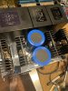
This is where @c_dk would shine. As this topic came up in the past, Chris explained the outputs could go into oscillation when using the wrong type of resistor for a given design.

You're obviously aware (as you mention it above) ... as I now see.
 
Indeed, and since my 2105 is still using all the original Motorolas, there is even less a chance of oscillation, compared to the 15003 replacements. As c_dk mentioned before, there is no lifespan for a semiconductor item like that. Other failure prone items, bad temperature or a short take them out. Since virtually everything will be replaced in this unit, they (and a few disc caps) will remain the only original items of concern.

I have verified that the 0.15 ohm WWs in my MC2205 are marked inductive.
 
Hmmm, I found what the repair was. One of the original 32-070 was replaced with a Motorola ClassA8. Date on that one is 1978, so most likely old stock at the place of repair. Anyone that pulled some good 32-070 to replace with 15003s want to sell a good one cheap? Even though it has worked for many years, with this one, until I can verify it is the exact same part as the original, I will wonder…

A guy is selling one on ebay for $40!! I can refit the entire amp with 12 MJ15003G from Mouser for $90, so that just may be what I decide to do if I suspect an issue.
 
Last edited:
A38CBE85-D0DB-4502-B484-692ADC92F2FA.jpeg

Well, finally finished mine up, at least as much as I plan for a while, as I replaced my MC2205 with it for now. (It will be my next Mac refresh). Very pleased with the results, thanks to Motnick and all for some good suggestions and subs. Mine still has the original 070’s and emitter resistors installed as everything measured well. No need to replace what is working well unless it will improve it. The main transformer hum is about 1/2 what it was. I also noted that my DC voltages to the new (Hayseed) multi cap are a bit high, like Moticks, 80V is 90, and 90 is 100. While on the big cans, 35 is 37, just beyond the 5% specified. So I suspect the big dropping resistors (100, 100, & 220) have probably drifted on the high voltages. I will just order some new ones & replace them and the rectifying diodes. Otherwise, it tested well, all voltages after the SS devices easily well within 5%.
My big cans both decay with no load in about perfect sync, taking about 2 minutes, similar to Gregs 2100 discussed. But with dummy loads on them, about 2 seconds, so minimal/no play on.

In my pics of the PO boards, I replaced the sentry transistors with MPSA14 & 64, as Motnick did, but then I read the 2100 thread about different resistors maybe needed for different Darlingtons. The hFE of the replacements was much lower than the originals which all tested good, so I put the old ones back in. The emitter voltages were all less than .05V speced. Also of concern was that MPSA66 is oft mentioned as the correct sub, not 64, so until I do more research…

Like Motnicks, many resistors on the PO board were drifted way out of spec, so I replaced them all with 1W metal film, except the 100ohms, which I kept as carbon 1/2W. Same with most in the input board, but found only 2 out of spec. Apparently temperature over the years has a profound effect on carbon resistors. The larger the value, the more accurate they still were. 10ohm units measured 12 ohm, and the 22 ohm ones measured 24-25. But 120k was 121k. Installed all 5% units except where 1% specified and the input resistors, which I made 1%. All the 5% metal resistors measured 2% or better.

The 3.6k wire wounds were within 5% so they stayed. I originally installed what I accidentally ordered, which were 5% 5W wire wounds, but not cement. They worked fine BUT I discovered another (obvious in hindsight) reason for the use of solder tubes. With the tubes soldered in, the PCB trace is locked against the PCB by the tube, which is collared on the opposite side. Without the tubes, the large 5W WWs I installed expanded when they got hot (normal) and each popped one solder pad off the PCB. I reinstalled the originals, and the pads are locked down again.

The audio of the amp is significantly quieter and sharper now. Just finished 2 hours at low normal listening levels, and it is basically like Motnicks, a degree or two above ambient, so it runs cooler now than it did. In the case, zero vented heat felt. Tomorrow I hope to put it through some more enhanced volume levels.

When tested playing a 1kHz sine wave at 36 watts, (about 16V to 8ohm dummy loads) the heatsinks got very warm/hot though not too hot to touch for a fair amount of time. Temperatures tracked nicely. The dual 50W dummy loads WERE too hot to handle, even in their safety cage.

Frequencies from about 1KHz to 12kHz could clearly be heard ringing in the amp at that level. I never noticed that in an amp before. Luckily, I don’t play 1kHz tones at that level on speakers!! Waveforms on the scope were symmetrical and clean.

The SM instructs calibration of the meters with 105W at +3dB. Since I wasn’t sure if a sine wave at 105W was safe, with a load on one side only, I opted to go to 1/4 power (14.4VAC into 8 ohms) and set the meters for -3dB. They were both low and non matching.

812E74E3-DA88-4C7A-8F1E-AEACBCB0CF3E.jpeg
 
Last edited:
Sounds like a success. Quick question. The service update calls for deleting C123 and C124, but yours are still there. Is this for any particular reason?
 
They are Deleted only for decks in a certain S/N range. Mine is a later S/N, so they stay. I am not learned enough to know offhand what they are for, I assumed, like most by-pass caps they are for stability. I would suspect that the transistors used in the affected S/N range were different models/makes and it was not required or caused an issue.

I’m still a bit astonished at the improvement in this MC2105. It has always worked, and it is in rather pristine shape for it’s age. I had replaced the glass like 12-13 years ago, and it has held up perfectly. (Just had a lot of bubbles. I kept the old glass.). I replaced the bulbs when I replaced the glass, so it looks great, and while it always sounded good, it ran a bit hot and it paled in comparison to the MC2205. Always a bit thinner. Maybe it’s the placebo effect or the “new shoes always look better” syndrome, but I swear it sounds better than the 2205 now!! Now I’m jonesing to get to the 2205 for the same treatment. The bass slam and details are definitely significantly improved. And a total lack of background noise, though I haven’t used headphones with it yet. Well worth the effort and cost, regardless.
 
Note 6 in the Service manual "Starting with Serial No. 26M08" states "C123 and C124 are not used in units with Serial No.'s 26M08 to 26M48. Mine is a mid year 1975 AH6701, so not in that range. But I just saw that on the Instructions for the 132-153/132-154 update the first line says "A. Delete C123-124". Thanks for pointing that out! I missed it completely when doing the work, which I now realize is the reason I did not order replacement ceramics for them, as I replaced all the others. DOH! Luckily they are easy to cut out once the cage is off.
 
Last edited:
Well, I went back in (and dang, even though the new big filter caps are 12oz lighter total than the originals, this thing seems heavier every time I work on it!) and swapped out the 100ohm resistors on the 170VAC feeds to the diodes. They were both still good (about 108ohms each). Very small decrease in DC voltage with new resistors : 80 V was 90V & is now 88V. The rectifiers are shown in the SM as 031s, but they were not on mine. Mine are 1N8420, of course NLA, but it shouldn’t be hard to find a sub if needed. They both still test good. I clipped out C123/4 as per instructions. (Thanks johnny_law!).

Glad I went in again, as I had forgotten to add an X2 suppression cap across the power switch (even though I use an SCR2 for powering on all the time, if I’m using headphones, I manually power off the amp and use them from the C33) and both sets of big filter cap screws needed a little bit of tightening.

I also went ahead and reflowed with fresh solder all the main leads, AC & DC.

And apparently when I had replaced the glass 13 years ago, I used #47 bulbs, (#1847 is long life version) which Terry had mentioned were an equivalent for the original #1866 on the lettering/power on bulbs. Those all seemed quite dim to me, not how I see in other pics online. Well, they are not exactly equivalent. The 47 series is 0.15 amp and the filament is closer to the base than the taller bulbed 1866 which is typically a brighter 0.25A. The design of the illumination is such that the filament has to be as close as possible to the inner flared opening of the plexiglass transmission diffuser. The 1866 puts the end of bulb & filaments MUCH closer to the plexiglass, plus are brighter. Replacing them with 1866s, returned the brightness back where it should be.

I hadn’t used the amp regularly in probably 8 years, due to the transformer hum and KNOWING I was playing with fire not updating such an old amp. As it turns out, all capacitors were still useable and only a few resistors had drifted well beyond spec, though most all in the output boards benefited from new one.

So even if it was safe to operate, I tested it only briefly before I dove in to it this time. It sounded fine, but as mentioned, the 2205 sounded much better.

Even though my 1974 dates main filter caps looked brand new, and measured uF wise, fine, as did the multi caps, I had replaced them all. Just knowing that all of them (all electrolytics) have to be degraded after 45+ years, I was still surprised to hear the difference. The resolding also dropped the transformer hum further, so it is now much quieter than say, a typical belt drive cassette deck! The bass is just phenomenally clear now, and I hope for similar results from my 2205. The restored 2105 definitely sounds better than the all original 2205. The clearer bass provides an illusion of better channel separation as the old bass signature seemed less channel dependent and more omni directional.

I had only paid about $500 for it, like 14 years ago (in a Mac cabinet) and all I did was replace the bubbled glass and put in the wrong bulbs. The hum seemed to bother me more as time went on, and then when I got the 2205, ($900 sans cabinet in 2009 IIRC) the plan was to sell the 2105. The cabinet went to the 2205. Fast forward through the years, And I just kept seeing Mac gear appreciate more and more, so it sat on a shelf, just appreciating.

When I started reading all these 2105 restore threads (old ones back then), and now many years more experienced in restoring analog gear, I figured there had to be a reason this amp was held in such high regard and maybe the problem was just old & tired components. So when another walnut case fell in to my lap locally for $100, I figure it was a sign to give it another chance. It only took me another 3-4 years to find the time, and reading Motnicks thread, to get me motivated enough to put in the time & effort.

I am SO glad I did. What a difference! And now with barely perceptible hum, I am really enjoying the heck out of it.
 
Last edited:
Glad I went in again, as I had forgotten to add an X2 suppression cap across the power switch (even though I use an SCR2 for powering on all the time, if I’m using headphones, I manually power off the amp and use them from the C33) and both sets of big filter cap screws needed a little bit of tightening.

Can you expand on what you did here? I've got no hum in a 2105 I'm working on and it sounds terrific (and puts out quite a bit more power than rated) but I get a nasty turn on thump on occasion with it.
 
Suppression caps help, but typically don’t do that much for turn on thump. That is inrush, and often due to the main filter caps. Have you replaced yours yet?

I installed a suppressor/resistor combination cap directly across the On-Off knob switch. That prevents arcing at the contacts in on & off transitions by providing a very small R-C network and limits the current during that small time constant. It’s main reason is to prevent burning of the contacts and wrecking the switch over time. I bought a couple for all the projects I do. They were around $5 each, IIRC. I will have to see if I took a picture of it and get the model/spec.

Also, how is the 2105 powered on? Ideally it is pre-amp first, then power amp on, for ON, and power amp off then pre-amp off, for OFF. Since I use an C33 preamp and the McIntosh SCR2, it provides a time delayed relay power on to the AC plug itself as well as switches speakers, so the 2105 power switch normally stays on all the time. I have zero thump of any kind at turn on.
 
Perry, this occurs if just sitting or connected. It is easily reproduced if it is switched back on quickly after powering off. The filter caps and multicap have all been replaced, as have all the input board and power board caps. It seems to be really hit or miss, none of my MC2100s do exhibit this behavior either. Outside of that, the amp sounds awesome. When I first got it, the input caps were toast, sound was distorted when cranked up. I also found that one of the ceramics on the input board was bad.
 
Well, yes, if I power on-off-on, there is definitely an inrush pop, and mine has done that since day one, before and after the recap, with or without the suppression cap, and powered by the SCR2 or not. I don’t know how that would be avoided without a time delay relay like on the 2205, and is what most amps have. The large filter caps discharge at different rates and the power supply coming back up at different levels is what does that. It doesn’t do it if all the caps have discharged completely and power up together. If yours does make a pop when fully discharged, and powered on (a reasonably small pop will occur) then the caps are not charging at near the same rate. There should be no pop if the levels pots are dialed down to zero. If there is, then there is an issue in the output amps somewhere.

I am surprised the 2100s don’t do it with on/off/on, as I always thought the amps were basically the same but without meters.

Maybe someone else has an idea?
 
Last edited:
Well, yes, if I power on-off-on, there is definitely an inrush pop, and mine has done that since day one, before and after the recap, with or without the suppression cap, and powered by the SCR2 or not. I don’t know how that would be avoided without a time delay relay like on the 2205, and is what most amps have. The large filter caps discharge at different rates and the power supply coming back up at different levels is what does that. It doesn’t do it if all the caps have discharged completely and power up together. If yours does make a pop when fully discharged, and powered on (a reasonably small pop will occur) then the caps are not charging at near the same rate. There should be no pop if the levels pots are dialed down to zero. If there is, then there is an issue in the output amps somewhere.

I am surprised the 2100s don’t do it with on/off/on, as I always thought the amps were basically the same but without meters.

Maybe someone else has an idea?

So I am going to try swapping the thermistors (they are reading low on resistance) when I left a leg on each of them. My 2100's read around 4 ohms each, my 2105 reads 1.8 and 2.3 respectively. Hopefully with getting that sorted, that issue will be less a problem.
 
Back
Top Bottom
