• The move to the new server is done. There are some software and database maintenance updates in process. This has us passing the hat around to help out. We appreciate any donations. Seriously, even a dollar helps. The payment page may be found here - https://www.audiokarma.org/support.html

MC2105 Rebuild

The barriers on the `terminal strip´ get broken when a slotted screw driver blade isn't relatively centered on the screw, and the torque will snap the barrier ends off. Typical of someone who can't see well.

That's the reason for replacing he screws with Phillips, they're self centering. But everyone knows that, right.


-Greg

You’ve convinced me to maintain the Philips screw upgrade. My Vessel JIS screwdriver really does fit them nicely. I was on the fence about disrupting the originality of the unit by using the Philips screws, but I have to be practical here. Besides this amp is far from original at this point anyway.

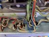
The main fix here was to get the solder repaired terminal out and also the spinning ground screw that would never tighten up fully. I couldn’t live with that! In the process I ended up with some much less chipped up terminal barriers.
 
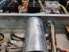
I was able to get the multi cap installed today. This is a nice solution from an installation perspective.

index.php

Hi Motnick im going thru the same rebuild you are g ive done everything minus the multi cap which comes in from hayseed any tips on removing the old one it seems like its soldered and theres rivets holding it let me know thank you and good job with the rebuild!
 
The original multi cap has some tabs that pass through the amplifier chassis and are twisted. In my unit only one tab was soldered to the chassis. I just removed the solder and un-twisted all of the tabs. After that the multi cap slides right out of the chassis. I did not have to mess with any rivets.

Here is the original multi cap removed from the amp.

index.php
 
The original multi cap has some tabs that pass through the amplifier chassis and are twisted. In my unit only one tab was soldered to the chassis. I just removed the solder and in twisted all of the tabs. After that the multi cap slides right off of the chassis. I did not have to mess with any rivits

Here is the original multi cap removed from the amp.

index.php

Ok thanks here i have attached pictures of mine i guess the flange thats riveted stays in place and the cap slides out does the hayseed cap also have the chassis tabs? Do the chassis tabs act as the ground for the cap or did you run a separate cable for that? Thanks for the quick response and all the help
 

Attachments

  • 20200502_154255.jpg
    20200502_154255.jpg
    110.5 KB · Views: 82
  • 20200502_154249.jpg
    20200502_154249.jpg
    102 KB · Views: 79
Leave the riveted flange alone. Just unsolder and twist the tabs. The new cap has tabs that will fit into the original holes. I twisted the new tabs and resoldered to the chassis.
 
I have been working on the input board the past few days. I’ve replaced some resistors that I found drifted and I have also replaced the capacitors. Should I replace transistors 132-092 and 132-056? I followed C_dk’s advice to replace them and delete the solder tubes on the driver boards and I’m wondering if I should do the same thing here on the input board.

index.php
 
Last edited:
What should I be using to clean the speaker selector switch? I have D5, F5, and G5 on hand. I’m thinking D5 followed by some G5 for protection, but I want to ask as I’ve read this switch can be a gremlin.

Also these tropical fish capacitors, C1 and C2. It looks like one is cracked to me. These should be replaced due to the crack, correct?

index.php
 
Last edited:
Signing to follow your project as I recently got a 2505. I have new electrolytic caps to install except for the main supply caps. My amp seems to work fine but I guess it is often a good idea to replace very old electro’s. The mains check fine for value and ESR.
John
 
Following thread. great stuff along with Gregorys 2100 thread. My 2105 has been unused for a few years now. Works fine, but all original except the big filter caps looked replaced. Also, there is some transformer hum that is annoying.
 
I have the input board completed now. I debated replacing the transistors on the input board but in the end I decided to remove the solder tubes and replace the transistors with KSC1845 and KSA992. The original transistors still tested good, but I did notice that the gain measurements of Q1/Q3 were a long way off. Q2/Q4 were still relatively close. The voltages in both channels of the input board are very even throughout the entire board now and they match up very closely to the voltages listed on the schematic.

index.php


I also replaced the capacitors on the meter board.

index.php


I cleaned the two gain control pots with Caig F5 faderlube, and used Deoxit D5 on all of the other controls followed up with some Deoxit gold. I replaced all of the lamps and cleaned up the lamp sockets with some D5 on a q-tip. I had to replace the power cord as the original was only about 12 inches long. The original owner told me that the power cord was damaged in a cabinet door about a year after he purchased the amp and he just shortened it as a solution. I used the eBay cord that another AKer had suggested in his Mcintosh thread.

index.php


I powered up the amp and let it idle on the bench for an hour. The heat sinks stayed cool. They all measured approx 2F degree above room temperature after an hour. Following that, I hooked up a preamp and listened to the amp for awhile. It is sounding very good and the heat sinks are just over 80F after a half hour of listening. I am going to listen to the amp a bit more and keep an eye on the heat sink temperatures with my temp gun before I put the cover back on.
index.php
 
Last edited:
What is the rationale for removing the solder tubes of the input board transistors? Just to get the extra solder connections out of the circuit, or something else?
Thanks,
John
 
What is the rationale for removing the solder tubes of the input board transistors? Just to get the extra solder connections out of the circuit, or something else?
Thanks,
John

They are a real pain to deal with. It’s a struggle to get all three transistor legs out of the solder tubes. I couldn’t imagine trying to solder the new transistors into the old solder tubes. To do a nice job you would need to heat all three tubes simultaneously, or somehow get all of the old solder out of the tubes.

I left the old transistors soldered into the tubes and just removed the transistors with tubes entirely from the pcb.

It would be interesting to know why McIntosh used the solder tubes to begin with. Seems like it would have doubled the assembly work for them. Solder the tubes to the pcb, and then solder the transistors into the tubes. :dunno:
 
Last edited:
Thanks. Just curious as one of these days I will update my MC2505. I have the parts but not the time right now.
John
 
Looks great, can I ask please did you just use regular auto wax on the black metal covers?

Mine have some light scratching so figuring out the best way to clean/restore, there's a mark over one of the decals from I guess the cabinet but I'll live with that.
 
Today I cleaned up all of the covers and put some auto wax on them. Finally I have everything reinstalled and looking good again.

The next step will be to clean up the wooden cabinet and get the amp back inside of it.

index.php


index.php


Very nice Motnick i finished mine a while back but for some reason it didnt sound right finally figured it out had to open the speaker on off switch and clean it with deoxit it would loose one channel intermitently and i thought it was my dac at first took me a while to figure it oht and it felt like it lacked power the switches are very serviceable but they are sealed so you cant just spray deoxit on them like most from the outside you have to push pack some tabs to open the case and then do it. After doing this it was a game changer power was back and it sounds incredible very happy with it! on hindsight I should have placed some jumpers on the speaker on off switch since i always have it in the on position and that way theres a full secure connection on both channels. I highly recommend cleaning it
 
They are a real pain to deal with. It’s a struggle to get all three transistor legs out of the solder tubes. I couldn’t imagine trying to solder the new transistors into the old solder tubes. To do a nice job you would need to heat all three tubes simultaneously, or somehow get all of the old solder out of the tubes.

I left the old transistors soldered into the tubes and just removed the transistors with tubes entirely from the pcb.

It would be interesting to know why McIntosh used the solder tubes to begin with. Seems like it would have doubled the assembly work for them. Solder the tubes to the pcb, and then solder the transistors into the tubes. :dunno:
The idea was to insert the iron between all three tubes in such a way that contact is made to each. Then the part swap takes seconds.
 
Back
Top Bottom