You are using an out of date browser. It may not display this or other websites correctly.
You should upgrade or use an alternative browser.
You should upgrade or use an alternative browser.
MC2105 Rebuild
- Thread starter Motnick
- Start date


So how does it sound now, Motnick?
Was it worth all the work? Inquiring minds want to know.
It sounds great. I have been listening to it nearly every day since I completed the rework. I have been using a C26 preamp and JBL L96 speakers with it. The C26 is in very nice shape but still all original. I’m thinking of going through the C26 next.
Last edited:
Motnick,
that MC2105 still going?
Yes, it still works great.
herecomesmd
New Member
Motnick,
Did you end up leaving R28,20,22 & 30 in place as they were or did you swap them to match the schematic? I have the same weird swapped resistors on my driver boards. Also, do you have a carbon comp resistor on the BACK of the driver boards that connect R6 & R8 as I do? I haven't seen that mentioned anywhere and have been wondering if that was an after-factory update someone made.
Did you end up leaving R28,20,22 & 30 in place as they were or did you swap them to match the schematic? I have the same weird swapped resistors on my driver boards. Also, do you have a carbon comp resistor on the BACK of the driver boards that connect R6 & R8 as I do? I haven't seen that mentioned anywhere and have been wondering if that was an after-factory update someone made.
Motnick,
Did you end up leaving R28,20,22 & 30 in place as they were or did you swap them to match the schematic? I have the same weird swapped resistors on my driver boards. Also, do you have a carbon comp resistor on the BACK of the driver boards that connect R6 & R8 as I do? I haven't seen that mentioned anywhere and have been wondering if that was an after-factory update someone made.
I followed the advice that I received here and left them as they were. No issues at all with that decision. My amp plays and sounds beautiful.
herecomesmd
New Member
Thanks. Do you have a resistor on the back of your driver board as well? It connects to R6 & R8. BTW, I have a 2100.I followed the advice that I received here and left them as they were. No issues at all with that decision. My amp plays and sounds beautiful.
Thanks. Do you have a resistor on the back of your driver board as well? It connects to R6 & R8. BTW, I have a 2100.
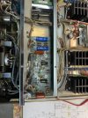
Yes, I believe that I do. You can see them in one of the pictures in the first post of this thread
herecomesmd
New Member
Ah! You are correct. It is there in your first post. Man, I'm surprised I missed that. Thanks!Yes, I believe that I do. You can see them in one of the pictures in the first post of this thread
Alright, well that seems like a pretty decent indication (in addition to the wisdom of others) that it was intentional from the factory. I had thought I found some one-off factory mistake and swapped the 1k/470Rs which also seems to work well but then later swapped back after I convinced myself it was intentional.
Now I should probably check to see if those back-of-the-board resistors are out of spec since they're staying. Those are the only resistors in the input and output boards I haven't checked.
herecomesmd
New Member
I ended up doing the same with Vishay Dale RN65s. I think you may have gone with thin films from what I saw in your photos. I think the temp coefficients are better on the thin films from what I've read.


Twirl
Just beginning
Went through the amp….all new caps. Changed the small value resistors & the bias resistors, along with the 3.6k on the output boards to metal film. All others were fine. All transistors remained original. The amp was a 1972 unit. Speced right out to 105 watts & clipped symmetrically at about 116 watts.
Used .047 PP bypass caps on the 2 640uf caps on the input board. Installed a new speaker switch & fixed the old one & moved it to the on off position.
Great little amp & fun to work on. My buddy is very pleased.
Used .047 PP bypass caps on the 2 640uf caps on the input board. Installed a new speaker switch & fixed the old one & moved it to the on off position.
Great little amp & fun to work on. My buddy is very pleased.