• The move to the new server is done. There are some software and database maintenance updates in process. This has us passing the hat around to help out. We appreciate any donations. Seriously, even a dollar helps. The payment page may be found here - https://www.audiokarma.org/support.html

MC240 - Back to Life

Bias board had two errors which I corrected this morning. Variac and an infrared thermometer and davids suggestion to check the voltage coming out of m209 before proceeding further showed me something was wrong. I will post a correct image. Btw you can connect a ground with a resistor to your multi meter positive probe and watch the caps drain down to ensure the circuit is safe. Probably not big news to many here. Otherwise I finished the power section rebuild and the amp plays again though when i use the variac to dial in 435v after m209, I get 308v and 128v at the next step downs at the filter caps instead of 300v and 125v. I still need to replace r60 and r61. Maybe I need a different value resistor between the A side of c25/c26 and the B side. Next is another check of voltages.
 
Jim gave me a 150K resistor for r57 as well as the 10K the design indicates. I will try the 150K now.

Another interesting note is that R56 gets hot and stays hot, almost 200F.
 
You must have a different schematic than I do, Chris. The ones on Berners do not have an R56. If a resistor is getting hot, there's a problem with too much current being drawn from something down stream from it.

Where, exactly, is this resistor on the chassis?

Cheers,

David
 
You must have a different schematic than I do, Chris. The ones on Berners do not have an R56. If a resistor is getting hot, there's a problem with too much current being drawn from something down stream from it.

Where, exactly, is this resistor on the chassis?

Cheers,

David

Just checked my schem, I also do not have a R55 or R56 on my schem.
 
My philosophy on this project is to retain as many components as possible and replace those that the voltage testing and resistance tests indicate are out of spec. However with the power supply its different because almost every person who has posted about these old amps says to make sure that is robust and delivering the proper voltages to the proper places. I read your entire thread and others about the resistors and good sprague caps on the audio board. I will retain as many of those as possible. Did you keep yours in case I need an old one in good condition? :)

I am changing my philosophy. I will be replacing all the caps now as a next step now that the power section rebuild is done. The voltages are still whacked out and I now only want to get into this thing once or twice and the use it.
 
I am changing my philosophy. I will be replacing all the caps now as a next step now that the power section rebuild is done. The voltages are still whacked out and I now only want to get into this thing once or twice and the use it.

Keep the black beauties. They are not electrolytic and most believe that they sound better than anything you could replace them with.
 
I ordered a kit which is primarily the russian K-40 caps and the 716p's along with some misc other parts. I will probably replace all but the black beauties at first and then work through whatever resistor issues may exist. I will use it for a while and then swap in the replacements for the black beauties and test that with my own ears! Thats the plan today anyway.

Can someone define exactly how I should be testing the voltages against the schematic? My line voltage is 121v which when I have the switch on the amp set to 125 has things running higher than the schematic suggests. If I use the variac and dial in 117 and have amp switch at 117 its all too low. Thanks.

Chris
 
I ordered a kit which is primarily the russian K-40 caps and the 716p's along with some misc other parts. I will probably replace all but the black beauties at first and then work through whatever resistor issues may exist. I will use it for a while and then swap in the replacements for the black beauties and test that with my own ears! Thats the plan today anyway.

Can someone define exactly how I should be testing the voltages against the schematic? My line voltage is 121v which when I have the switch on the amp set to 125 has things running higher than the schematic suggests. If I use the variac and dial in 117 and have amp switch at 117 its all too low. Thanks.

Chris

I used the variac to dial in my B+ (435vdc) and then measured all other voltages. Don't know if this is correct, it is the method I choose. I did find that if a measurement was off, rechecking the B+ showed that it had drifted. I don't know if that was a result of transformers warming up or source voltage drifting. It was pretty unstable so I often found my self readjusting the B+ to measure other points.

In real life situations, unless you supply the exact voltage all the time, the system voltages will not be operating at optimal voltages.
 
I used the variac to dial in my B+ (435vdc) and then measured all other voltages. Don't know if this is correct, it is the method I choose. I did find that if a measurement was off, rechecking the B+ showed that it had drifted. I don't know if that was a result of transformers warming up or source voltage drifting. It was pretty unstable so I often found my self readjusting the B+ to measure other points.

In real life situations, unless you supply the exact voltage all the time, the system voltages will not be operating at optimal voltages.

So for this amp you are measuring the voltage at the "A" side C25/C26 with the ground connected to the chassis?

I will say the voltage is rock solid on mine so far.
 
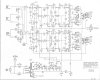
This schem is a bit different. I think I got it from Jim when he sent the parts list files for the rebuild kits. It has a few minor differences and a couple unexplained notes with corresponding dotted lines. I'm not sure if it is any value to this discussion but here it is.
 

Attachments

  • mc240.jpg
    mc240.jpg
    91.2 KB · Views: 25
This schem is a bit different. I think I got it from Jim when he sent the parts list files for the rebuild kits. It has a few minor differences and a couple unexplained notes with corresponding dotted lines. I'm not sure if it is any value to this discussion but here it is.

I saw that somewhere as well but am using the one you posted so my circuit looks like that schematic now and it plays.

I tell you what I could really use is the location of R60 and R61. I think I have them traced up on the main signal path board but have not finalized those replacements. I appreciate everyone's help on this.
 
I saw that somewhere as well but am using the one you posted so my circuit looks like that schematic now and it plays.

I tell you what I could really use is the location of R60 and R61. I think I have them traced up on the main signal path board but have not finalized those replacements. I appreciate everyone's help on this.

I have that documented somewhere. If I recall correctly they were on the main resistor/cap board, not where you would expect them to be on the power supply section.
 
I do have R61 documented from an email I had sent to Jim.:

r61. You can see it in this pic, middle row, above the 12k resistor. GreenBlueRedGold running horizontally.

attachment.php


I thought I had numbered all the resistors on the board but I only have their values. R61 the 56K running from term 20 to 18 middle row.

attachment.php
 

Attachments

  • .jpg
    .jpg
    84.7 KB · Views: 88
Thats exactly what I needed. Thats what I thought R61.

I had R60 as the vertical resistor between 20 and the board center.
 
Back
Top Bottom