• The move to the new server is done. There are some software and database maintenance updates in process. This has us passing the hat around to help out. We appreciate any donations. Seriously, even a dollar helps. The payment page may be found here - https://www.audiokarma.org/support.html

MC2505 catastrophe

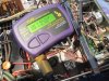
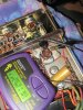
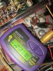
I don't think I'm measuring the multi caps correctly; I get different values depending on which 2 terminals I connect to the ESR70. On C34, should the probes be connected the way I have them in the picture (D + gnd)(triangle + gnd)?

I've searched online but couldn't find anything on where to connect the probes in order to properly test multi caps. I can get different values on C33 depending on how I connect the probes. If I connect D, square and triangle to ground I get 45.63uF (1.06 ohm); 48.52uF (1.00 ohm) and 47.64uF (1.08 ohm) respectively. If I connect the post with no symbol (ground?)to the nut that holds the cap, I get 67.04uF (0.77 ohm).

On C33, clip one lead to a common can twisted lug and the other to a shape.
 
Measure C33 like this. One lead on a twist lug, then move the other lead to the four “shape terminals” (half moon, triangle, square, dash etc) and take a reading for each.

There are four twist lugs that are common and are twisted during install to secure the cap in place.

8E165EAC-298A-4DFA-AECF-79F7A258D488.jpeg
 
C33 (connected as you indicated above):
triangle- 172.2 uF / 0.37 ohm
square- in circuit/leaky / 0.45 ohm
D- in circuit/leaky / 0.35 ohm
no symbol- 66.97 uF / 0.75 ohm
 
ESR on C33, the four section can, looks normal as does ESR on the two GE 9300uF cans. We need more AKers to weigh in on C34, the two section can. C34 ESR seems high. This might indicate that C34 has a fault, but I’m not sure.
 
Last edited:
I went back and looked at your photos measuring C34. I think you measured both sections correctly. It looks to me like common on that can was wired to the "nothing" terminal with no shape, instead of a twisted common can lug.

Reading 6 ohms on both sections of C34 suggests a potential problem with that can. You could carefully desolder the wires from that can and take another Atlas measurement of both sections of C34 with the can out of circuit. This would tell you accurate capacitance of each of the two sections. Sometimes capacitance reads incorrect if measured in circuit. We don't know if the one section that measured 104.4 uF in circuit is a true reading or not, but that is way low for either section, and it's another lead indicator that C34 may be bad and requires more testing.

If you test C34 out of circuit and don't see capacitance in reasonable tolerance of 200uf and 500uf, C34 is likely bad.
 
Last edited:
How did the rectifier diodes test?
D19 to D22: 2 diodes test at approx 0.5v / OL, the other two test at approx 0.5v / 1.5v
D23 to D26: they all test at approx 0.5v / 2.0v

I assume they are not all showing OL in reverse because they are in circuit?
 
I went back and looked at your photos measuring C34. I think you measured both sections correctly. It looks to me like common on that can was wired to the "nothing" terminal with no shape.

Reading 6 ohms on both sections of C34 suggests a potential problem with that can. You could carefully desolder the wires from that can and take another Atlas measurement of both sections of C34 with the can out of circuit. This would tell you accurate capacitance of each of the two sections. Sometimes capacitance reads incorrect if measured in circuit. We don't know if the one section that measured 104.4 uF in circuit is a true reading or not, but that is way low for either section, and it's another lead indicator that C34 may be bad and requires more testing.

If you test C34 out of circuit and don't see capacitance in reasonable tolerance of 200uf and 500uf, C34 is likely bad.

ok, I will try that; signing off for tonight however; time for dinner. Many thanks again Monk!
 
The schematic you posted on the prior page shows C34, the suspect two section FP can cap, filters the -44 V supply node.

Question for 2505 experts, if C34 has failed, could it cause the issues Benz is experiencing?
 
Last edited:
One the later 1972 2505 I have, C79 (C34 on Benz's 1968 model) filters Q11 and Q12, both T066 packages. On the 1972 model, these two transistors are on the left and right output boards. Are these the driver transistors?

On @Benz 1968,these two transistors use the chassis as a heat sync instead of driver boards on the later models. See photo Benz's 2505 below.

If Benz's C34 cap filters the node for the two T066 driver transistors pictured, and if C34 (the two section FP can cap) failed, could it cause the issues he is observing?

20230425_183444.jpg
 
Last edited:
The C34 can section that tested 104 uF is the "half moon." Half moon in this can is first section after the rectifier. That section is supposed to be 200 uF. So, in circuit, it's only testing 52% of the nominal factory value. It's interesting that both sections (200 uF and 500 uF) are each testing out at about 6.5 ohms ESR. I wonder if C34 has a short.

8.jpg
 
I took some readings this morning of C33, having trouble with this camera... so hopefully am able to post --photos.
My C33 had issues and Terry Dewickt did his magic underneath with regard to C33... will hopefully find the charger for my camera i know better so you can see regarding C34....

Not a lot of time to review all this, BUT thought I would at least contribute what I can for now.....
Ye,s Benz, you are on your way to coming up with a resolution.
Your big filter caps still look ""ok" ...

Peak instruction manual has a reference guide to ESR readings -- took a pic, lets see if I can post it. its in your owners manual as well...peak esr sheet.jpg

yay --- success..
View attachment 2876821
peak esr sheet.jpg


Here are my C33 readings...


In any event, your leaky high esr cap -- sucks -- uhh not having the time today to follow throughout the schematic... (i suck at schematic inerpetation --) That is a definite place to eliminate --- just as my goofy readings on my images shown today my cap has gone south.....

I really need to sit down and compare things ---

An item of mine -- and will certain be one of yours is --- according to the service man you posted -- see (nder potentiometers) R1, R2 (DC Balance ADJUST)
Those/ and the procedure will become important...

Lets hope this post with all the nutty images of mine prove some assistance --

Celadon....peak esr sheet.jpg diode term.jpg half moon.jpg triangle.jpg square.jpg
 
Last edited:
@Celadon it looks like DeWick might have replaced your C34 (or C79 depending on serial number) FP 500 uF can cap section with that 470uF 100v gold colored radial Nichicon in your picture. If so, it's more evidence that the C34 (or C79) FP can cap is prone to failure. On the early models, C34 is a two section can (500 uf and 200 uf). On mid-production serials, it is renumbered C79 and only consists of one 500 uf section inside the can. I've read that in the final 2505s, the factory installed C79 for cosmetic reasons only--and the can wasn't even connected electrically! All of this is anecdotal evidence that the MAC factory worked to gradually eliminate the C34 (C79) FP can from the 2505 circuit over time.
 
Last edited:
@Celadon , your Atlas meter is covering up your C34 (C79) can. Can you post a photo of that can and the ESR readings you are getting? Which serial range is your 2505? I'm curious if DeWick disconnected that can or electrically tacked in that 470uf gold Nichicon because that FP can failed.
 
@Celadon it looks like DeWick might have replaced your C34 (or C79 depending on serial number) FP 500 uF can cap section with that 470uF 100v gold colored radial Nichicon in your picture. If so, it's more evidence that the C34 (or C79) FP can cap is prone to failure. On the early models, C34 is a two section can (500 uf and 200 uf). On mid-production serials, it is renumbered C79 and only consists of one 500 uf section inside the can. I've read that in the final 2505s, the factory installed C79 for cosmetic reasons only--and the can wasn't even connected electrically! All of this is anecdotal evidence that the MAC factory worked to gradually eliminate the C34 (C79) FP can from the 2505 circuit over time.

Thank you so much for your information-- as, I still like after ~20 years am unable to determine the unit's Serial number it has long been polished off before I owned it.

Without the time today to process your mentionings, it sounds like -- I bet you are correct.

Let me say --

I sure do not want to hijack Benz - thread, he sure seems to be making progress - and your help, as well as others --gonna make this happen.

But
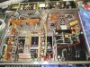
-- As a reference here is a better complete shot of underneath --

I believe you are correct, as C34 is completeley dead -- and used as "terminal only".
The nichicon and ( I presume, the black one @ the left.) make what were originally the can cap.

mc2505-2.jpg
 
Thank you so much for your information-- as, I still like after ~20 years am unable to determine the unit's Serial number it has long been polished off before I owned it.

You can approximate the serial number of your unit by looking at the date codes on the wire wound cement resistors. These are the off-white rectangular resistors with red print under the heat syncs. If you post a close up of those resistors, we can get a date off them.
 
Last edited:
I believe you are correct, as C34 is completeley dead -- and used as "terminal only".
The nichicon and ( I presume, the black one @ the left.) make what were originally the can cap.

It seems that after 40 or 50 years, C34 is a prone to failure component. Looks like @Benz might be experiencing a similar failure that DeWick fixed in your unit. What's the capacitance and voltage rating of that black radial cap DeWick added near C34? It also looks like DeWick found some rectifier diodes and carbon comp resistors in your power supply out of spec, as several appear to have been replaced.
 
Last edited:
Yikes stripes !!! how cool is that --
Im jumpin --
You can approximate the serial number by looking at the date codes on the wire wound cement resistors. These are the off-white rectangular resistors with red print under the heat syncs. If you post a close up of those resistors, we can get a date off them.
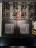
date code.jpg

6807 ? could that be july 1968 ? .....
LOL - this unit IS marked 2505-2 with flat glass.
 
Last edited:
Back
Top Bottom