• The move to the new server is done. There are some software and database maintenance updates in process. This has us passing the hat around to help out. We appreciate any donations. Seriously, even a dollar helps. The payment page may be found here - https://www.audiokarma.org/support.html

McIntosh MX 112 FM/AM Stations Suddenly Gone

richardg0n

Active Member
Greetings AK,
I was listening to FM stations on my MX112 and noticed FM reception began fading and a short while later I could no longer receive FM stations. I noticed the tuning tube is still on but no longer fluctuating while tuning in stations. A few years ago I recapped the power supply canister, power supply circuit board, and left and right preamp boards. I don't have experience troubleshooting FM IF board or MPX Circuit board. I have Oscilloscope, DMM, and Schematic. Should I invest in a signal tracer to troubleshoot? Looking for advice. Thank you.


Richard
 

Attachments
  • 9376C5BD-A4A6-403A-94ED-BC523AFE5B06.jpeg
    9376C5BD-A4A6-403A-94ED-BC523AFE5B06.jpeg
    202.5 KB · Views: 23
Last edited:
Register to hide this ad
Did you lose both AM and FM as the title of the thread says? Or just FM?

Have you checked whether you can still pass a signal from aux or phono input? If PH and aux both fails the same way, something's up in the main portion of the preamp. If Aux is OK, but phono fades away like the FM does, then the issue is in the portion of the phono preamp that the AM and FM also run through.

Have you tried to see if the mono or HF/LF filters make any difference when the problem occurs?
 
Did you lose both AM and FM as the title of the thread says? Or just FM?

Have you checked whether you can still pass a signal from aux or phono input? If PH and aux both fails the same way, something's up in the main portion of the preamp. If Aux is OK, but phono fades away like the FM does, then the issue is in the portion of the phono preamp that the AM and FM also run through.

Have you tried to see if the mono or HF/LF filters make any difference when the problem occurs?

Hi Bob,
AM is also not working, I hear nothing on AM, and on FM I hear static. The tuner is not picking up any stations. Tested the Aux and phono, and they work fine with no issues. mono and HF/LF filters have no effect on Tuner. Filters are working on AUX and Phono.
 

Attachments

  • IMG_3715.jpg
    IMG_3715.jpg
    105.1 KB · Views: 3
^^ This. Second thing, check the power supply voltages.

Checked Voltages on power supply cans

The Main can was gutted, and I installed CAPS in the can a few years ago.

Sprague 066-128 - Main Power Supply(previously recapped)

200 VDC Half Circle - 105VDC
150 VDC Square - 160 VDC
50 VDC Triangle - 44.1VDC
50 VDC Blank - 42.4VDC


Center Channel Power Supply(original and not recapped)

Mallory 066-129
100 VDC - 72.3VDC
100VDC - 15.5VDC

I would have to pull the can from the board to identify which one is the half circle or triangle.
 

Attachments

  • IMG_3716.jpg
    IMG_3716.jpg
    138.4 KB · Views: 6
  • IMG_3717.jpg
    IMG_3717.jpg
    85.2 KB · Views: 6
Let's make it easier on all of us... what are the voltages at the circled points on the PS board. The 16V supply section on the left supplies 16V to the tuner and the right PS supplies the preamp. Let's
see what you have coming out of the PS, particularly the left portion.

upload_2023-1-20_14-35-36.png
 
Both sections of that C204 can should be up in the 72 range so that 15V measurement is a concern, unless that's a measure from C201 over in the 16V supply in which case at least it's close. C210 C and D are in the 150 and 110 range, so those might be good. C210A is spec'd at 40 there, so I think your 44s and 42s are probably good.

The key is that 16V, that feeds parts of AM/FM directly and feeds a switch that feeds the rest of the AM and FM when you've got it selected on the front panel. That 16V is unique to the tuner and if it's not there it'd explain why both are out. I can imagine that C201 electrolytic may have failed which would not allow the 16.7 to build and the regulator's pass transistor wouldn't pass the 16V. Q201 may have quit, or ccould also be shorted out on the tuner end.

If you measure at the pins as suggested, or use the component reference designations, it'd be a bit easier to follow.
 
Let's make it easier on all of us... what are the voltages at the circled points on the PS board. The 16V supply section on the left supplies 16V to the tuner and the right PS supplies the preamp. Let's
see what you have coming out of the PS, particularly the left portion.

View attachment 2772944

The power supply board in this unit is 043868 and is different than the schematic you posted. It only has 7 points on the left. Pin 8 is not used on this board. Point #17 had no measurable power, and I see in the schematic that C204B should be supplying 100VDC, which could be one of the problems. Pins 5,6, and 7 had more than double the power.

The measurements are as follows
#1 - 41.1V
#2 - 42.6V
#3 - 33.9V
#4 - 33.9V
#5 - 35.1V
#6 - 35.2V
#7 - 35.3V

#13 - 128.7V
#14 - 128.9V
#15 - 162V
#16 - 106.1V
#17 - 0 - no measurable power at this point
#18 - 71.5V
#19 - 71.5V
#20 - 9.2V
#21 - 9.2V
#22 - 8.5V
#23 - 8.5V
 
Last edited:
Q201 is probably shorted, and has put 35V on your tuner circuitry instead of the expected 16V. I would expect perhaps more damage, including certain semiconductors and electrolytic capacitors in the tuner circuit. Power off, measure resistance between the collector and emitter of Q201 and report back. Or, D201 is open. Measure voltage, power on, from Q201 base to ground and report back.

Pin 17 should be zero, it's grounded. Pins 13-23 supply power to the preamp which seems to be working OK, let's focus on the tuner PS for now. They are two completely separate units.

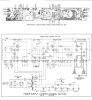
Since this is apparently a different circuit board than what's in the manual, could you post a picture of both sides of it?
 
Q201 is probably shorted, and has put 35V on your tuner circuitry instead of the expected 16V. I would expect perhaps more damage, including certain semiconductors and electrolytic capacitors in the tuner circuit. Power off, measure resistance between the collector and emitter of Q201 and report back. Or, D201 is open. Measure voltage, power on, from Q201 base to ground and report back.

Pin 17 should be zero, it's grounded. Pins 13-23 supply power to the preamp which seems to be working OK, let's focus on the tuner PS for now. They are two completely separate units.

Since this is apparently a different circuit board than what's in the manual, could you post a picture of both sides of it?


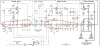
Q201 is open(no continuity) and base reading is 19V. any idea what could cause Q201 to fail? I also desoldered one of the legs on D201 and measured 1.29 with my DE-5000. I uploaded the schematic and printed circuit board. Early service manual is from serial numbers starting 10S01.
 

Attachments

  • 743BF462-1B93-40B9-B4C4-E9A1A58AB5D3.jpeg
    743BF462-1B93-40B9-B4C4-E9A1A58AB5D3.jpeg
    133 KB · Views: 11
  • 3926A6E1-5D0D-471F-A11E-B343CF754033.jpeg
    3926A6E1-5D0D-471F-A11E-B343CF754033.jpeg
    134 KB · Views: 10
Last edited:
OK, thanks for the updated schematic. If you have 19V on the base that's kind of close enough, and I don't expect the diode is bad. Should be 16.7V, but my bigger concern is the 35V issue.

You have 35V on pins 5, 6, and 7 which is a strong indication that Q201 has a collector-emitter short. The 40V output from pin 1 only seems to drive the stereo light, and I don't see that it can backfeed into the 16V unless there were several transistors that had unusual failures in the MPX circuit. To make sure it's not, you could remove the stereo light bulb from its socket.

Let's double check your voltage on pins 5, 6, and 7 to ground. Also double check the chassis ground connection for the red/yellow wire coming from the power transformer as well as the ground for that portion of the power supply board. Not sure if it's a screw, nut, wire, or what. Check resistance to chassis ground from C201 negative terminal.

Finally put your meter in AC mode and see what you get at pins 1 and 2 to ground, and make sure there's not a lot of ripple there.
 
OK, thanks for the updated schematic. If you have 19V on the base that's kind of close enough, and I don't expect the diode is bad. Should be 16.7V, but my bigger concern is the 35V issue.

You have 35V on pins 5, 6, and 7 which is a strong indication that Q201 has a collector-emitter short. The 40V output from pin 1 only seems to drive the stereo light, and I don't see that it can backfeed into the 16V unless there were several transistors that had unusual failures in the MPX circuit. To make sure it's not, you could remove the stereo light bulb from its socket.

Let's double check your voltage on pins 5, 6, and 7 to ground. Also double check the chassis ground connection for the red/yellow wire coming from the power transformer as well as the ground for that portion of the power supply board. Not sure if it's a screw, nut, wire, or what. Check resistance to chassis ground from C201 negative terminal.

Finally put your meter in AC mode and see what you get at pins 1 and 2 to ground, and make sure there's not a lot of ripple there.

Removing the stereo light bulb had no effect on voltage readings.
I double-checked the readings and tried grounding to others area of the chassis and still no change to higher voltage readings 5,6, and 7. The reading was 35.5VDC on all.
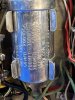
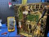
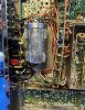
Checked the ground to power supply and transformer and didn't note any issues with ground connection(see attached pics).
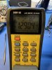
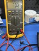
I removed C201 and checked capacitor and found no problem in test with my Fluke 87v(see attached pic).
I checked AC.
pin 1 - 48-62VAC
pin 2 - .6VAC
 

Attachments

  • 79488646-2228-486E-BA93-7FC7BCF9293D.jpeg
    79488646-2228-486E-BA93-7FC7BCF9293D.jpeg
    174.2 KB · Views: 11
  • 8608B73E-CD34-4FF5-99AC-BD9C638251C0.jpeg
    8608B73E-CD34-4FF5-99AC-BD9C638251C0.jpeg
    189.3 KB · Views: 11
  • 3C22C237-4500-4ACD-8154-E52D9F9FB598.jpeg
    3C22C237-4500-4ACD-8154-E52D9F9FB598.jpeg
    138.1 KB · Views: 10
  • 5778687F-E671-41E0-9CFD-D23D288204F2.jpeg
    5778687F-E671-41E0-9CFD-D23D288204F2.jpeg
    125.6 KB · Views: 9
OK, I see several issues. C201 is measuring 73 uF where it should be 100. You should be seeing NO AC at all on pin 1, which means either C210A is bad, or its ground connection is bad. I see that the can capacitor, which I presume is C210, is simply clipped to the chassis.

w3jn said:
Check resistance to chassis ground from C201 negative terminal.
Did you do this? What did you find?
 
OK, I see several issues. C201 is measuring 73 uF where it should be 100. You should be seeing NO AC at all on pin 1, which means either C210A is bad, or its ground connection is bad. I see that the can capacitor, which I presume is C210, is simply clipped to the chassis.


Did you do this? What did you find?


I needed to confirm resistance check. Do you want me to do that with C201 in circuit? Red lead on C201 negative and black lead on chassis ground?
 
Last edited:
Yep. Just want to ensure that there's good ground contact on that part of the PS circuit.

Let's also check resistance between pins 2 and 5, and then between pin 5 and ground.
 
Yep. Just want to ensure that there's good ground contact on that part of the PS circuit.

Let's also check resistance between pins 2 and 5, and then between pin 5 and ground.

Resistance readings

Pin 2 + 5 = OL
Pin 5 + Ground = 441.2
C201 + Ground = 0.3
 
Excellent! We've established that the 16V line going to the tuner isn't shorted to ground, and that Q201 isn't shorted, and the board has a decent chassis ground.

I have the following concerns still: The 35V on the 16V line; the 45V or so AC on pin 1. We want to see if there's an AC component on pin 5.

Let's put your meter in ACV, power on, and measure pin 1 to ground, pin 2 to ground, and pin 5 to ground. Could be we have bad filter capacitors and that regulator is very confused, but Q201 is still a concern.

Do you have a couple of 100 or 200 uF capacitors laying around you could temporarily connect between pin 1 and ground, and pin 2 and ground? If you see considerable AC voltage from pin 1 or pin 2 to ground, you can try temporarily connecting them with clip leads and see what you get on pin 5 (maintaining polarity - minus goes to chassis ground).
 
Excellent! We've established that the 16V line going to the tuner isn't shorted to ground, and that Q201 isn't shorted, and the board has a decent chassis ground.

I have the following concerns still: The 35V on the 16V line; the 45V or so AC on pin 1. We want to see if there's an AC component on pin 5.

Let's put your meter in ACV, power on, and measure pin 1 to ground, pin 2 to ground, and pin 5 to ground. Could be we have bad filter capacitors and that regulator is very confused, but Q201 is still a concern.

Do you have a couple of 100 or 200 uF capacitors laying around you could temporarily connect between pin 1 and ground, and pin 2 and ground? If you see considerable AC voltage from pin 1 or pin 2 to ground, you can try temporarily connecting them with clip leads and see what you get on pin 5 (maintaining polarity - minus goes to chassis ground).


Pin 1 + Ground = 51VAC
Pin 2 + Ground = .612VAC
Pin 5 + Ground = 1.2VAC

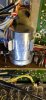
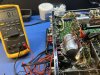
100uf 25V clipped on to Pin 1 + Ground + Pin 2 + Ground = 0.1VAC on Pin 5(see pic)
 

Attachments

  • 3BC58BB9-57A7-443E-A754-967769DBE201.jpeg
    3BC58BB9-57A7-443E-A754-967769DBE201.jpeg
    158.9 KB · Views: 9
OK, that 25V cap isn't gonna last long at 50V going into it. With that, we've determined that the capacitor connected to pin 1 is bad. What's strange here is that pin 1 has 51VAC and pin 2, which is the first filter right after the rectifiers, has little AC voltage on it.

I neglected to have you measure the DC voltage at pin 5 with that capacitor clipped in. Check the capacitor you used to clip in first to make sure it hasn't shorted. If you have a 50V capacitor instead (anywhere from 47 to 300 microfarad, or put two of those 100 uF in series: +][-+][- ) clip that one in, and measure pin 5 DCV. Hopefully with some filtering that will settle down the regulator circuit and we'll get 16V out of it.
 
Back
Top Bottom