• The move to the new server is done. There are some software and database maintenance updates in process. This has us passing the hat around to help out. We appreciate any donations. Seriously, even a dollar helps. The payment page may be found here - https://www.audiokarma.org/support.html

McIntosh MX 112 FM/AM Stations Suddenly Gone

First, it looks like you can repair that choke, see the circled area in the pic below, it appears that wire has broken. You can pull off a half turn of wire from the choke so you can re-solder it, or bridge it with a short piece to fix it.

Second, man I wish I knew you had a signal tracer - woulda made some of this easier!

Third, I think the Sencore (if working) would be best since it does stereo. The HP would be excellent for the front end and IF, but not much help to align the MPX. The HP 8656A is a beast of a sig gen, with absolutely top-notch quality. But there are downsides to it, namely the attenuator can get funky, and complexity of repairing it if it craps out. I'd offer the guy a hundred and if so, that'll get you close and you'll have something that will serve you well for years.

Fourth, bummer that the LO isn't working, apparently.

Last, the ICs seem to be drawing a bit more current than expected. You might need to round up a couple of CA3012s. Be advised (as I mentioned) these are a giant PITA to replace, because of the ten pins in a circle. Getting all the pins aligned into the holes is no fun. To remove them, I'd just clip all the leads (but note beforehand where the tab on the IC case is siutated), then pull the leads one by one. If you have a good vacuum desolder station that'll make short work of it though.
View attachment 2803130

I'm going to solder the choke per your recommendation.

Regarding signal tracer, I recently purchased but was sitting in the shipping box until a week ago. Out of sight out of mind. Sorry about that.

Thank you for the buying advice. I purchased a "Mint" SG165 on eBay but suspect it will need to be recapped and calibrated. I was not able to meet with seller of HP 8656A and instead opted for a newer signal generator also purchased on eBay. A.B.O from Japan(see attached), it was a unit used at the Pioneer test labs in Ohio. I opted for this signal generator because it's newer and hopefully less prone to repairs. My plan is to use this with the SG165's MPX if need be. I think I'm done buying test gear for now....LOL.

I also found NOS RCA CA3012's on eBay and will install them when they arrive.

I will circle back and check in once the CA3012's are installed. Thank you for you help
 

Attachments

That's a pretty nice sig gen! I have a RE125 that does AM stereo, RDS, etc as well as several HP sig gens (HP 8640B, HP 8664A, HP 3325A).

Good luck with those CA3012s, last time I replaced a 10 pin can like that it took me an hour to get all the pins inserted right. I got it in once and then discovered I was off by one pin, so I had to do it all over again....
 
That's a pretty nice sig gen! I have a RE125 that does AM stereo, RDS, etc as well as several HP sig gens (HP 8640B, HP 8664A, HP 3325A).

Good luck with those CA3012s, last time I replaced a 10 pin can like that it took me an hour to get all the pins inserted right. I got it in once and then discovered I was off by one pin, so I had to do it all over again....

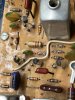
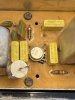
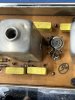
Installed CA3012's. I could not solder the external wire wound wire so I instead installed a replacement choke(see pictures). The MX powers up but no change to the tuner section. SG165 just arrived and going to open it up to make sure there are no leaking caps before I power it on. What are your thoughts about the next steps?

IMG_3993.jpg IMG_3989.jpg IMG_3994.jpg
 
Let's take voltage readings at the CA3012 pins again, and see if anything has changed. THe next step will be to shoot a 10.7 MHz signal to the input of the IF board and see what we get.

Doubtful that the SG165 has bad caps but it's always good to do a visual. Test it out by connecting a hank of wire to the output, tune the thing to somewhere in the FM band, and use another FM radio to pick it up. You should be able to get a feel for how to use it.

WHen testing stuff out it's always best to start with a small signal and go up from there. Here, I'd start with about a -60 dBm (or 60 dBF, depending on how the output is calibrated), which is a medium-strong signal, 10.7 MHz, mono, 1 KHz modulation, 75 KHz deviation. Note that there's 17V at that point, so feed it with a .01 or so capacitor in series. The actual value of the cap is unimportant - anything from .05 down to .001 should work fine. We just don't want DC to get into the generator. That's something to keep in mind as you might end up injecting a signal directly into a circuit - ALWAYS use a series capacitor with your generator unless you're connecting to the antenna, or you know 100% there's no DC in that area. Your generator might have an internal series capacitor but most do not, and have DC coupling through to the resistive attenuator. If you put healthy DC on the attenuator you'll fry it. Ask me how I know THIS..... the mistakes of youth....
 
Back
Top Bottom