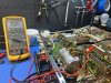
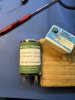
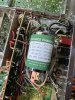
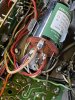
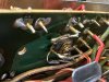
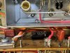
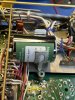
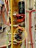
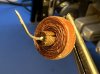
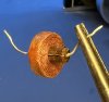
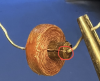
OK, the muting adjust pot is in parallel with L101, but there's a 270 ohm resistor in series with it so if l101 was bad, and the muting adjust was all the way over at one end, it would read 270 ohms. Perhaps removing L101 damaged it. The choke is wound on a phenolic form and the enameled wires are likely wrapped around the leads very close to where they emerge from the form. If it's indeed bad, try heating directly at the point where the leads enter the form, and add a touch of solder. However could also be that overcurrent destroyed L101. Here are some replacements if need be
https://www.ebay.com/itm/225238544788?hash=item3471437194
Now that we've established Q101, Q102, and the diodes are good, we can try shooting an audio signal into TP2 to see if audio makes it thru the MPX board. Should have done this before, I guess. See if there's any DC voltage at TP2. There shouldn't be, but it's best to check. If there isn't any DC voltage, feed an audio source (CD player, another tuner, audio from your phone, etc) into TP2. Make sure MONO is selected. If we get audio when it's in FM mode then the MPX board is passing audio. That doesn't mean quite yet it'll work in stereo, but we can then proceed to the IF board.
Now might be a good time to try and round up a sig gen. For the IF we'll need one capable of 10.7 MHz and FM modulation. Lets also check the voltages on the rest of the pins of IC1 and IC2 on the IF board.
Another thing, might as well check to see if the local oscillator is working. Tune the MX to 88 MHz, then take a portable FM radio, put it as close to the FM RF section as possible, and tune the portable to 98.7 MHz (88+10.7). Hopefully you'll heard a dead carrier on the portable radio (ie a signal that quiets the radio, but has no modulation), and if you tune the MX a little bit the carrier should also shift around.