• The move to the new server is done. There are some software and database maintenance updates in process. This has us passing the hat around to help out. We appreciate any donations. Seriously, even a dollar helps. The payment page may be found here - https://www.audiokarma.org/support.html

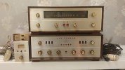
MF-300 & Remote Control Acquired

I have worked on building an Op Amp board to take the place of Q1, Q2 and M3 modular circuit portions of the RK-20 receiver front end. This has taken a number of days off and on since I am also working on installation of a 5.6KW solar panel system. Today I removed M3 along with Q1 and Q2 plus C1, a .47uF@10VDC. The R10 shown as a 4.7K ohm resistor inside M3 is actually an external resistor mounted on two metal pins above the circuit board. I don't know if the original M3 design including R10 proved to be a problem area and someone removed it as part of a repair or if it proved troublesome and the factory decided to mount a 1/2W resistor externally for better reliability.

I am lacking some 4.7K and 2.7K ohm resistors plus some more .1uF capacitors to complete the installation of the Op Amp sub-board, so those will get ordered from Mouser later today.

I will create a schematic of the dual Op Amp in Photoshop later today if possible and post it here. At present it consists of two inverting stages in series using 10K input resistors and variable 250K ohm multi-turn controls to adjust the gain of each stage. I suspect the maximum gain will not be needed and once overall gain of the two stages has been adjusted for the needed level of sensitivity and stability, I can use fixed resistors to handle the gain of each stage.

Here is a photo showing the receiver board prepared to receive the Op Amp board. It will use the existing -15VDC power supply in the unit in a manner similar to the Op Amp approach to implement a TL82 Op Amp and create a preamp output for the 500-C or 800-C receivers. The red lead will bring the -15 volts to the circuit and the black lead will be the positive ground connection.
RK20 prepped for Op Amps web.jpg
You can see R10, the 4.7K ohm resistor along the bottom edge of the RK-20 PC board on pegs.

Joe
 
There were delays in getting parts ordered until this morning. I did some searching through the various parts I had on hand and managed to locate a 30K ohm resistor to take the place of R9 and a precision 1% resistor (which measured 2625 ohms) to take the place of R11. I had a .1uF@100V to take the place of C5. I will have to wait for the parts to arrive to take care of replacing R20 to establish the bias of Q3. R9 and R11 were installed above board. C5 was installed under the board. The space needed for the board I built for the Op Amp will just fit within the remaining space topside. I wanted easy access to adjust the gain of the Op Amp stages.

I did some measurements of the resistor values in the M3 component and see that a number of the resistor values are not as marked but were within 10% tolerance of indicated values. I did not bother trying to measure the capacitors inside the unit. Not bad results for a unit of this age.

Joe
 
so op-amps replace all of the apparently missing parts on the circuit board? I'm guessing those original parts are troublesome, or is this to add some gain to make up for the lower output of the rebuilt transducer?
 
It is to provide additional gain to make up for lower output of the remote hand unit. The original parts were still functional and worked OK with Matt's remote hand unit. Unfortunately my unit which has its transducer rebuilt does not have the same level of output even though the frequencies are correct.

Joe
 
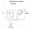
I was unable to repair the ultrasonic transmit transducer in the remote control hand unit. So I am into plan B now. I found that Murata makes a set of ultrasonic transducers intended for use in automobile proximity detectors. It operates in the 40kHz region just like the original transducer and oscillator circuits in the Fisher remote hand unit. I bought one set of these from Mouser Electronics. I bought a set of 555 timer ICs from eBay and have built up an ultrasonic oscillator.
555 Ultrasonic Oscillator.jpg
The resistor values and the capacitor values between IC pin 7 and pin 2 to ground provide the ability to use the .0027uF cap at both the 38.285kHz and 41.805kHz frequencies used in the original Fisher hand unit and RK-20 receiver. When the original hand unit was rotated 90 degrees from horizontal and the channel or volume button was pushed it engaged a second oscillator circuit that modulated the channel or volume frequency by a secondary 120Hz frequency. This lower frequency was detected by a low frequency detector in the RK-20 and caused another relay to be engaged which changed the motor direction of the appropriate motor in the MF-300.

Pin 7 of the 555 timer IC is its "reset" pin. It is used mostly in designs where the the timer IC is in Mono-Stable mode. I am using them in their Astable mode (continuous wave as long as the IC receives power). I plan to try using this pin to be modulated by a second 555 timer operating at 120Hz. The output signal is applied currently direct to the Murata ultrasonic transmit element MA40S4S. The output of the 555 timers is a square wave pulse. A certain amount of resistance (100-600 ohms or so) in series with the feed to the ultrasonic transducer helps tame the ragged response of the transducer to the square wave. However, it does at the same time reduce the amplitude being fed to the transducer. I have not had the chance to see just how much energy the ultrasonic transmit transducer puts out. I am using a common 9V transistor radio battery for now. I like the simplicity of the 9V transistor battery. The 555 timer ICs will accept up to about 18VDC, but I think that would be pushing it a bit too much. An alternative to get more AC voltage out of the IC would be to use a 12V battery made up of a stack of AAA batteries in a plastic holder. Another alternative would be to use one of the low cost audio transformers as a step-up device. There are a number of them that are designed to operate from 300Hz-100kHz that could be employed. Using a transformer might also cut down some on the square wave raggedness when connected to the transducer.

Right now I have the circuit bread-boarded on an experimenter's board from Jameco. It allows me to change parts at will until I find what provides the most stable frequency along with ease of tuning. The tuning is being done with a 10-turn 2K ohm variable resistor in series with a 4.7K ohm resistor. The 4.7K ohm resistor puts the oscillation operating in a range that allows the variable resistor to adjust the frequency with fine enough adjustment to get the frequency output of the oscillator within a few Hz of the ideal. It is also possible to adjust frequency by using a ceramic trimmer capacitor, but most of the ones available at reasonable cost produce rather large jumps while adjusting them in circuit. The resistor trimming method seems to be easier to do. Temperature stability of the capacitor is a parameter I will be looking at. I need to find types that have the least change with temperature. Of course, in an average home the temperature changes are not expected to be extreme, but I do need to choose the ones that have the least change over temperatures of say 40 degrees F to 90 degrees F. 90 degrees would be rather uncomfortable for most of us and I doubt we would experience that very often in our homes. We would hopefully not be listening to our audio equipment at such temperature extremes.

The goal is to ultimately be able to put all the pieces of the hand unit inside a plastic project box about 3" X 5" X 1" complete with battery pack.

Joe
 
Is that how those 1960's remotes operated? Using ultrasonic oscillators? For some unknown reason I always thought it was via infrared light. I remember when you pressed a button the remote made a loud clanging sound and inside there were these long cylindrical metal bars that moved. So the TV's had receivers for those oscillations. I'll have to investigate and fill that hole in my knowledge. Nice to see you active again, Joe. Been a while. Thorne
 
Infrared was what replaced ultrasonic. Once LEDs became a thing, it was much cheaper to just flash an LED than to deal with building an oscillator and transducer to make it all work. The very earliest ones were actually RF based. The remote for my 1939 Philco has a one-tube radio transmitter built into the remote and it pulses the output using a mechanism that is very much like a rotary phone.
 
I don't know how I've managed to miss this article so far. I've been in possession of am MF-300 for some years now.
I also have all the remotes and the ultrasonic receiver. I'm actually bringing up the unit slowly on my variac now, as I
type this. I haven't used the receiver for a couple of months maybe. But, last time I did it was all working fine.
The only slight problem being that when searching for stations the mechanism is a bit noisy/clunky. The automatic
search reversal works ok too.
What an absolutely fantastic contribution to this site. I am so appreciative of the people here on AK that take the time
and trouble to post their experiences on this forum.
Top notch stuff!
Jim (West Sussex, UK)
 

Attachments

  • myf.jpg
    myf.jpg
    17 KB · Views: 3
Back
Top Bottom