• The move to the new server is done. There are some software and database maintenance updates in process. This has us passing the hat around to help out. We appreciate any donations. Seriously, even a dollar helps. The payment page may be found here - https://www.audiokarma.org/support.html

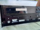
Missed it by that much, a Yamaha RX-300U struggles to rise again

Those Nichicons look like a good choice also. Thanks for sharing!
You're ahead of me; I have responsibilities for another week or so before I'll have any time for fun hobby stuff. (end of semester)

Are you going to replace any other smaller caps while you're at it? (I can't find a schematic anyplace, by the way. Hoping not to need it though but it would be nice to have.)
My experience has been that usually the smaller caps go before the bigger caps, so if this were a unit that I was restoring then yes. And in your case I would recommend it. However I wasn't really planning on restoring this, so I am not sure how far I may go. I do have a large stock of smaller caps, I will probably look through them and see if I have good replacements on hand. This is a pretty simple unit without too many e-caps, so definitely maybe.
 
Those Nichicons look like a good choice also. Thanks for sharing!
You're ahead of me; I have responsibilities for another week or so before I'll have any time for fun hobby stuff. (end of semester)

Are you going to replace any other smaller caps while you're at it? (I can't find a schematic anyplace, by the way. Hoping not to need it though but it would be nice to have.)
 
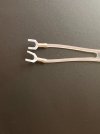
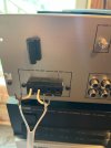
Kind of a silly question but I wonder if anyone has a suggestion - these 300 ohm dipole FM antenna connections don't fit in the RX-xxxU terminals. However, they do work great in my other receivers. Plus, I suspect that the wire is too fine to clamp properly if I cut them off and strip the insulation.

I suppose I'll just cut them off and solder a piece of wire on the ends, and have one antenna for Yamaha and another for everything else, but I thought it was worth putting out there in case there's a good idea.

(My rx-300u gets pretty good reception with just a piece of speaker wire stuck in there actually.)

IMG_0291.jpeg
 
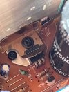
Mine has developed some strange dropping out issues that I thought was the relay (and probably is to an extent!). I finally got time to get the board out and have been looking for any visible issues . . . it does have this strange "carbonization" of the flux (?) across a few traces, like in the picture. So I'll clean that up. I wonder if that's causing some of
the erratic behavior in the amp. I've only worked on older stuff and haven't seen anything like this.

IMG_0343.jpeg
 
Last edited:
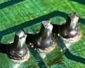
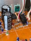
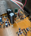
Well . . . here's a close up of the voltage regulator pins. The tuner was getting power intermittently when I pressed down on the heat sink. (I really need to get some good magnification so I can see better. This was hard to see!) Zooming in with phone camera really shows fractures - no wonder the contact isn't good. Some reflowing is definitely in order. I suppose there's a good deal of heat there. I wonder if this voltage regulator supplies power to the tuner. If so, that explains the problem I've had.

IMG_0543 v3.jpg
 
The failed solder joints are on the D1913 transistor that's screwed onto the heat sink.

Is this transistor a voltage regulator?

There's a Youtube of an RX-300U repair of the exact same issue but worse than mine . . . I guess this component takes a lot of heat. I wonder if it should be replaced and if so, with what. I'll probably remove it and test and make sure there's grease on the surface for good contact.
(I also ordered a relay and the new caps suggested above, so waiting for those.)

IMG_0370.jpeg
 
I got it finished.

The new relay works great and I used the Nichicon 5600uF caps. Scraping the old glue took patience and I'm sure I scratched the board a little. I just used IPA, 99%. Probably spent an hour on that glue. The only parts I changed were those two caps and the relay.

It sounds fantastic in my opinion!

I also reflowed a lot of solder pads. I think the main issue with mine was the transistor legs in the picture in #25. I pulled the transistor and tested it, and cleaned all around that spot and put fresh compound on it. The board flexes a lot and I think this receiver gets pretty warm so maybe this is a typical failure point.

Maybe the relay was actually not the problem but the one recommended by @avionic works fine! I also cleaned all the controls and pots again, with D5 then F5 . . . not sure that was the best strategy but there is absolutely no static now.

The window came out of the face plate with just a razor blade as it was held on with two sided tape. That was nice to get clean so it looks good! I used 4 dabs of E6000 to reattach it. I don't like the automotive-style push pins that hold the control boards in but oh well, I got it all back together.

There is something about the way these sound. So incredibly "clean". No noise floor. The bass extension and variable loudness are just so cool. I think the tuner works very well too. They fly below the radar for sure in the vintage receiver value chain - maybe because of the styling. I'm used to listening to 70s receivers that are very cool, and I love them, but they probably have a lot of distortion. This Yamaha is just refreshing and engaging to listen to for a change. Fun project! I think these are worth fixing and we should save them.

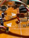
Image.jpegIMG_0547.jpegIMG_0546.jpegIMG_0557.jpeg

My solution for the antenna, not the best but it works:
IMG_0494.jpeg
 
On mine, Left was 4.9mV and Right was 5.3mV. I adjusted them both to 9.3mV. Does that seem right?
IDK, do you have a service manual? I haven't gone to look for one yet. I think that with a distortion meter one can watch distortion and take the bias down until distortion starts to rise. I haven't done that myself yet.
 
Thanks for posting @Asmodeus2112. It's cool that we're saving these RX-300U's and it's too bad the original post was about giving up.

I'm enjoying mine a lot.

I attempted a bias adjustment, FWIW. Right (red) is VR104 and left (green) VR103. I soaked the trim pots in fader lube first. I gather that we'd be looking for ~8 mV to 10 mV DC across both resistors. On mine, Left was 4.9mV and Right was 5.3mV. I adjusted them both to 9.3mV. Does that seem right?

View attachment 3779754
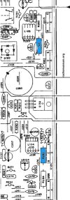
I don't think that seems right. The test points are just across one resistor, not two.
1781057816935.png
 
I don't think that seems right. The test points are just across one resistor, not two.
View attachment 3779970
Thanks, that's really helpful. I didn't have the manual - couldn't find it on HiFi Engine, so I was just going by AI which was wrong apparently (I'm not surprised). I'll have to redo my adjustment. I don't see markings on the board for the resistors, to find the correct one, but I'll look more closely. Thanks @Asmodeus2112

I deleted the incorrect information from post 31 in order to not confuse anybody should someone use this thread in the future.
 
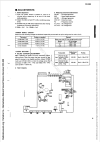
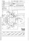
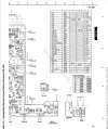
I reached my limit of 3 downloads in 24 hours, so was only able to get half of the PCB layout. I'll get the other half and the rest of the schematic later.

Keep in mind that this is from the bottom looking up, so it's mirror imaged from how we see it looking down.
1781095340476.png
 
Thanks again @Asmodeus2112

I agree, Radiomuseum does look very good.

That certainly confirms: for idling current adjustment, 8mV-15mV DC across each of the green interior resistors below.

(I'm loving the transparency or detail or clarity - whatever the term is - in this receiver, with headphones. "Bass Extension" is just a subtle boost to me; really nice. The famous Yamaha variable loudness is awesome. I think I only paid $14 for this receiver. Unbelievable.)

2026-06-11_07-47-39.jpg
 
Back
Top Bottom