

You are using an out of date browser. It may not display this or other websites correctly.
You should upgrade or use an alternative browser.
You should upgrade or use an alternative browser.
Missed it by that much, a Yamaha RX-300U struggles to rise again
- Thread starter FrankyLttrs
- Start date


I decided to check DC offset.
Left: 30.8mV DC
Right: 77.9mV DC
The right channel is borderline too high. That's a bit of a bummer! Maybe some more parts need to be replaced. Did you check your DC offset @Asmodeus2112 ?
Left: 30.8mV DC
Right: 77.9mV DC
The right channel is borderline too high. That's a bit of a bummer! Maybe some more parts need to be replaced. Did you check your DC offset @Asmodeus2112 ?

Asmodeus2112
Super Member
Left: 9.1mV DCI decided to check DC offset.
Left: 30.8mV DC
Right: 77.9mV DC
The right channel is borderline too high. That's a bit of a bummer! Maybe some more parts need to be replaced. Did you check your DC offset @Asmodeus2112 ?
Right 15.1 mV DC
Nice!Left: 9.1mV DC
Right 15.1 mV DC
Mine is all put back together now - I should have checked DC offset earlier, while it was all apart.
From what I gather, the RX-300U doesn't have any adjustment for this.

Last edited:
Asmodeus2112
Super Member
Did you test the DC offset without any speakers connected? Tone controls to 0, volume to 0, Input to tape or something quiet?
Yes - I re-checked it following these steps to be certain and got the same results.Did you test the DC offset without any speakers connected? Tone controls to 0, volume to 0, Input to tape or something quiet?
1) turned on and let it idle at 0 volume with no inputs for 40 minutes.
2) bass extension off.
3) bass and treble at defeat
4) loudness "flat"
5) source = CD
Left 31.0 mV
Right 77.2 mV


Try it without a source connected.5) source = CD
Thanks @avionic and @Asmodeus2112
Sorry I meant the "Input" selector was on CD. No actual source was connected to the RCA inputs, for those readings.
I appreciate any suggestions - it would be great to track down the parts that need to be replaced. It does sound great though!
Sorry I meant the "Input" selector was on CD. No actual source was connected to the RCA inputs, for those readings.
I appreciate any suggestions - it would be great to track down the parts that need to be replaced. It does sound great though!

I'm late to this party. Is the hood put back on now? Wanted to suggest some things.Here's the new relay and caps.
View attachment 3776412
Hi @Soundscape - thanks, you're not late!I'm late to this party. Is the hood put back on now? Wanted to suggest some things.
I did put it all together and have been listening to it . . . then I got the idea to check DC offset, figuring that it was probably ok, since it sounded so good.
I'd be glad to take the hood off though! Thanks for any suggestions! If we get those measures lower, maybe it'll help the thread be a resource for other RX-300U owners who may come across this.
Asmodeus2112
Super Member
I haven't done a ton of work trying to fix DC offset in an amp that doesn't have an adjustment circuit. But reading it seems like various different components in the circuit could cause it. Transistors of course, bad diode, resistors. This thread has some info as a starting point with a couple users describing their work that corrected high DC offset.
 www.diyaudio.com
Amplifier DC Offset - How Much is OK?
Interesting thread guys. I've been working on my Carver TFM-55 power amp that had a 350mV dc offset on the left channel. (right was 3.5mV which is great for a 15 year old amp) The main culprit was a small diode 1N4148 malfunctioning. This was passing positive charge up through the negative...
Asmodeus2112
Super Member
I intend to join the radio museum.org and get the rest of the SM and schematics sometime soon.
Asmodeus2112
Super Member
IMO, this DC offset isn't affecting the sound quality. If anything, it might reduce the output level where the amp clips, but unless you are listening at close to max output power likely a non-issue.Hi @Soundscape - thanks, you're not late!
I did put it all together and have been listening to it . . . then I got the idea to check DC offset, figuring that it was probably ok, since it sounded so good.
I'd be glad to take the hood off though! Thanks for any suggestions! If we get those measures lower, maybe it'll help the thread be a resource for other RX-300U owners who may come across this.
I appreciate you guys!
@Soundscape - Thanks for your interest! You made some good points about going over the board again (now I don't see your post however). The gaps between areas are very small and so are the pads. (I've wanted to get a digital microscope - hmmm this seems to be Fathers Day weekend . . . do you guys use those?). First I tried cleaning with cotton swabs and they left some lint so subsequently I cleaned that off with a microfiber cloth, and did use 99% IPA which cut the old flux well. That was before buttoning it up. Anyway, there could certainly be an issue remaining on the board. These boards seem to flex a lot and it seems that the unit generates a lot of heat.
@Asmodeus2112 - thanks again for your awesome suggestions and help with manuals! I've been downloading bits and pieces from RadioMuseum as well.
I wonder, in this circuit, is there a "differential pair" or "LTP" (as in the link) that need to be hFE matched?
I agree, as good as it sounds (IMO), I'm not worried, but in the spirit of learning it would be a nice contribution (and fun) here to dial that in. This is where I struggle - understanding the circuit well enough to figure out what to do beyond cleaning and replacing parts. (I think I have a basic understanding of what transistors, resistors and capacitors "do" but I'd like to improve my understanding of circuits.) Maybe this is a good unit to learn from.
Evidently, a bunch of Yamaha receivers from this era that use a similar circuit. There aren't that many parts involved!
@Soundscape - Thanks for your interest! You made some good points about going over the board again (now I don't see your post however). The gaps between areas are very small and so are the pads. (I've wanted to get a digital microscope - hmmm this seems to be Fathers Day weekend . . . do you guys use those?). First I tried cleaning with cotton swabs and they left some lint so subsequently I cleaned that off with a microfiber cloth, and did use 99% IPA which cut the old flux well. That was before buttoning it up. Anyway, there could certainly be an issue remaining on the board. These boards seem to flex a lot and it seems that the unit generates a lot of heat.
@Asmodeus2112 - thanks again for your awesome suggestions and help with manuals! I've been downloading bits and pieces from RadioMuseum as well.
I wonder, in this circuit, is there a "differential pair" or "LTP" (as in the link) that need to be hFE matched?
I agree, as good as it sounds (IMO), I'm not worried, but in the spirit of learning it would be a nice contribution (and fun) here to dial that in. This is where I struggle - understanding the circuit well enough to figure out what to do beyond cleaning and replacing parts. (I think I have a basic understanding of what transistors, resistors and capacitors "do" but I'd like to improve my understanding of circuits.) Maybe this is a good unit to learn from.
Evidently, a bunch of Yamaha receivers from this era that use a similar circuit. There aren't that many parts involved!
Asmodeus2112
Super Member
I like messing around on lower in the line components for this reason. If you want to learn, the stakes are low as long as you stay safe. Assuming that the circuit design is good, and these systems left the factory with lower DC offset than what you are measuring, some components may be off. If you have the SM schematics, they have expected voltage values printed on one channel. You could carefully probe around (Use mini grabbers, power off when connecting/disconnecting) from the PSU forward and see if you have any variance. Next I would say would be to understand the circuit and test various components. In that DIY Audio thread one person swapped some components from one channel to the other and saw the dc offset change. Have fun. If I can help by probing voltages on my unit to compare or something I am happy to.I appreciate you guys!
@Soundscape - Thanks for your interest! You made some good points about going over the board again (now I don't see your post however). The gaps between areas are very small and so are the pads. (I've wanted to get a digital microscope - hmmm this seems to be Fathers Day weekend . . . do you guys use those?). First I tried cleaning with cotton swabs and they left some lint so subsequently I cleaned that off with a microfiber cloth, and did use 99% IPA which cut the old flux well. That was before buttoning it up. Anyway, there could certainly be an issue remaining on the board. These boards seem to flex a lot and it seems that the unit generates a lot of heat.
@Asmodeus2112 - thanks again for your awesome suggestions and help with manuals! I've been downloading bits and pieces from RadioMuseum as well.
I wonder, in this circuit, is there a "differential pair" or "LTP" (as in the link) that need to be hFE matched?
I agree, as good as it sounds (IMO), I'm not worried, but in the spirit of learning it would be a nice contribution (and fun) here to dial that in. This is where I struggle - understanding the circuit well enough to figure out what to do beyond cleaning and replacing parts. (I think I have a basic understanding of what transistors, resistors and capacitors "do" but I'd like to improve my understanding of circuits.) Maybe this is a good unit to learn from.
Evidently, a bunch of Yamaha receivers from this era that use a similar circuit. There aren't that many parts involved!
Mine is all back together and sounding great. I am rebuilding my workbench and I am going to put it through it's paces. Max output, distortion, etc. as I put my test equipment back together. (and possibly aquire some new test equipment...)
homedetectiv
New Member
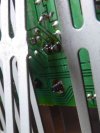
Thank you for sharing this. I found the same problem in an old RX 300U I fished out of a metal dumpster yesterday. Tuner, display, and phono preamp did not work while the power amp and tone controls worked fine. Mine was dinged up pretty badly from being thrown into the dumpster so instead of taking it all apart, I cut through the ventilation grill directly under D1913, folded back a portion of it, and resoldered the pins. IMHO, the pins are too stiff for this application and unable to bend with temperature swings. Also, there was some sort of hardened liquid around these pins only on the trace side. I cleaned off as much of it as I could. Oh, and before I did anything, I tested the PN junctions on D1913. It tested fine. Until I read your post here, I had no idea that none of the three pins was even connected. Thanks again.Well . . . here's a close up of the voltage regulator pins. The tuner was getting power intermittently when I pressed down on the heat sink. (I really need to get some good magnification so I can see better. This was hard to see!) Zooming in with phone camera really shows fractures - no wonder the contact isn't good. Some reflowing is definitely in order. I suppose there's a good deal of heat there. I wonder if this voltage regulator supplies power to the tuner. If so, that explains the problem I've had.
View attachment 3766432
Attachments
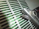
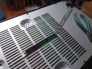
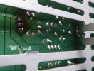
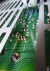
Cool!Thank you for sharing this. I found the same problem in an old RX 300U I fished out of a metal dumpster yesterday. Tuner, display, and phono preamp did not work while the power amp and tone controls worked fine. Mine was dinged up pretty badly from being thrown into the dumpster so instead of taking it all apart, I cut through the ventilation grill directly under D1913, folded back a portion of it, and resoldered the pins. IMHO, the pins are too stiff for this application and unable to bend with temperature swings. Also, there was some sort of hardened liquid around these pins only on the trace side. I cleaned off as much of it as I could. Oh, and before I did anything, I tested the PN junctions on D1913. It tested fine. Until I read your post here, I had no idea that none of the three pins was even connected. Thanks again.
I'm glad you saved it.
The hardened liquid is cooked flux. You can clean it off with IPA, 99%. I think there must be a lot of old Yamahas of this late 80s/ 90s vintage that don't get a lot of love, don't work right but are pretty easy to fix and sound absolutely great. Also - it's not too difficult to get the board loose and flip it over so you can completely clean and inspect, if you'd ever like to do so.

That's a good point! The aluminum tab that Q130 is screwed to is part of the huge heat sink - you would think that's pretty good heat sinking but maybe not. I put new compound on mine and cleaned it up, FWIW, and tightened that screw.Looks like that regulator needs larger heat sinking if possible.
or maybe raise the existing heat sink up off the board a little so there can be a little air flow under it. Might help keep it a bit cooler and
not heat stress the solder joints.
