• The move to the new server is done. There are some software and database maintenance updates in process. This has us passing the hat around to help out. We appreciate any donations. Seriously, even a dollar helps. The payment page may be found here - https://www.audiokarma.org/support.html

Mixed up phono1 with aux1 after having disconnected everything

Hi Dankik,
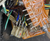
As said, I opened the receiver in another way now by removing the two front plates. It was to avoid having to fight with the two boards that have to be connected with each other from underneath. Because of the way I opened now, I have way less overview and worse, a green wire came loose from position J409. This time my picture didn't save me because the angle it was taken made it not clear to what pin I have to reconnect it. I'll show you the picture. I think it have to be connected with the other green wire on the middle pin but I am not 100% sure. Could you see that from the schema? I'll show you the connector. After that, I could upload all pics I already made in the process. thumbnail_IMG_3853.jpg
 
Sorry I may not have been clear, no lamp burnt. I meant the lamp in the dial pointer doesn't go out anymore (It should go out when shifting to aux or another non radio position).
 
Isn't that Aux not only 1 showing input L+R and output L+R? Whereas Phono is specifically mentioned Phono 1 and 2? Forgive me if I do not understand.
 
Hi Dankik,
As said, I opened the receiver in another way now by removing the two front plates. It was to avoid having to fight with the two boards that have to be connected with each other from underneath. Because of the way I opened now, I have way less overview and worse, a green wire came loose from position J409. This time my picture didn't save me because the angle it was taken made it not clear to what pin I have to reconnect it. I'll show you the picture. I think it have to be connected with the other green wire on the middle pin but I am not 100% sure. Could you see that from the schema? I'll show you the connector. After that, I could upload all pics I already made in the process. View attachment 2763193

I believe this problem is solved, it must be the first pin, I was lucky to find a picture from another member:
https://audiokarma.org/forums/index.php?attachments/img_6844-jpg.2435624/
 
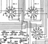
According to the schematic, J409 should only have two wires on it (on pins 2 & 3)
Note: My line colors have no meaning to the wire color.
  • J409 Pin 1 is not connected, should be open
  • J409 Pin 2 goes to J413-3 (Red)
  • J409 Pin 2 goes to P200/J213 (Red)
  • J409 Pin 3 goes to P200/J224 (Blue)
  • J409 Pin 3 goes to P200/J206 Pin 3 (Blue)
upload_2023-1-10_20-42-55.png
 
Make sure you put them on in the right order. According to the other photo, the way you have it in your picture is the opposite order, correct? J409 has the yellow wire and should be near the edge of the board.
upload_2023-1-10_20-59-7.png
 
I think there is a problem with this schema. I can now for sure tell that the depictions of the selector switch are not according to my model hence what else is different? See below where I marked the pathways with red arrows that are missing in the schema but do exist on my S401-1 F! thumbnail_IMG_3834 (1).jpg S401 1.jpg
 
I'm not sure that I can be of any help. Maybe you can get photos from the member in your other thread to provide photos of wiring.
https://audiokarma.org/forums/index.php?threads/marantz-2385-e-need-help-restoration.982716/page-2

**** Never Mind - I see in the other post that @merkan corrected it later ****
Is this connector with the purple wire in the correct location?
  • Looks like your purple wire is on the outside connector and the pink wire in toward the wafer switch.
  • But if you look at the 2nd photo from the referenced thread it looks the pink wire is on the outside connector and the purple is closest to the wafer switch.
upload_2023-1-11_8-19-38.png

See this one from here:
https://audiokarma.org/forums/index.php?threads/marantz-2385-e-need-help-restoration.982716/
upload_2023-1-11_8-22-8.png
 
Last edited:
I'm not sure that I can be of any help. Maybe you can get photos from the member in your other thread to provide photos of wiring.
https://audiokarma.org/forums/index.php?threads/marantz-2385-e-need-help-restoration.982716/page-2

**** Never Mind - I see in the other post that @merkan corrected it later ****
Is this connector with the purple wire in the correct location?
  • Looks like your purple wire is on the outside connector and the pink wire in toward the wafer switch.
  • But if you look at the 2nd photo from the referenced thread it looks the pink wire is on the outside connector and the purple is closest to the wafer switch.
View attachment 2763629

See this one from here:
https://audiokarma.org/forums/index.php?threads/marantz-2385-e-need-help-restoration.982716/
View attachment 2763630

I asked the other member for the input selector positions but he has not answered or maybe not seen it. I can fully understand if you think you cannot help me further, but you have been such a great help so far. I am going to put it back together again for the last time tonight (my health starts to suffer from skipping sleep) and am now contemplating my final strategy. What strikes me is that problems have gone worst after tampering with the input selector, i.e. at first, only the aux1 and phono1 were messed up (maybe one wrongly placed molex after all?). Now the system behaves even more erratic. I cannot imagine that I have mixed up al lot of cable connections, I found one that may have been wrongly placed due to the same color combination and corrected that the last time. That leaves me thinking if the secondary and third waver should be flipped 180 degrees after all, as it probably was when only aux and phono were mixed up. I wanted to upload all my pics in a gallery but couldn't figure it out yesterday how to do so (probably because of exhaustion). Thank you so much so far, I,ll keep updating this thread so people may avoid the same mistake I apparently made.

Cheers
 
Last edited:
the pathways with red arrows that are missing in the schema but do exist on my S401-1 F!
It could be that the connection goes to through the wafter to the contact on the back side then established contact with the wiper and down to the interface pins.
 
I see an irregularity at j403 406!

***** I see now from the timestamp that that mistake was on monday, yesterday they were grouped correctly*****


IMG_3761.JPEG IMG_3763.JPEG IMG_3794.JPEG
 
Last edited:
On a side node, I also have a 2250B from which I opened the input selector not long time ago and have good pictures. I now compared the pictures with the schema in the service manual section European model, and come to the conclusion that these schemas are totally unreliable when it comes to the input selector at least! Waver 3 and 4 are matching in shape, but if you look in the schema in the service manual, waver 2 and 4 are matching. The question now is how I can rely on the schema from the 2385. At this point really nothing is working.


upload_2023-1-12_17-37-17.png IMG_3683.JPEG
 
Here is my attempt at comparing the (E) schematic with the board layout connectors and wires.
The schematic diagram may not be 100% correct, but that was what I started with.
This might help you to find any wiring errors.
Screenshot 2023-01-12 102353.jpg

Screenshot 2023-01-12 102533.jpg

Screenshot 2023-01-12 102719.jpg
 
Last edited:
It is fully working!!! All inputs function correctly, no scratchy sounds, left and right channel sound equal. Yesterday night I tested it with the tone board hanging outside the device (just what I see pro's doing on youtube) and even the radio didn't give sound anymore. Today I thought let me be on the safe side and test it again, this time with the tone board fixed and did not change anything else hence it's difficult to pinpoint what made the difference.

Going to fix some details like the stereo indicator bulb seems to have ceased and the tuner cord, then close everything. I'll come back later with some pics or even audio if that is possible.
 
One small problem left, the stereo indicator doesn't work, also not with a new bulb.
 
Last edited:
I think the Stereo Lamp is V004 and it connects to J071 then to J412 Pin 2 which goes to S401-1R. Check to make sure that the connector of J412 is seated correctly. Does the Stereo Lamp come on at all for Phone, Tape, Aux or only when trying to tune in a Stereo FM station?

Looking at the schematic, there also appears to be a fuse (F853) in line with V004. If you can, check it.

upload_2023-1-12_16-15-25.png
 
Last edited:
Back
Top Bottom