• The move to the new server is done. There are some software and database maintenance updates in process. This has us passing the hat around to help out. We appreciate any donations. Seriously, even a dollar helps. The payment page may be found here - https://www.audiokarma.org/support.html

Modern Power for Tube Projects?

linuxslate

Well-Known Member
I'd like to know what the AK collective thinks of using something like this as a power supply for a basic P-P EL84 or similar Power Amp project?

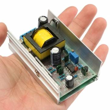
https://www.banggood.com/DC-DC-Boos...ge-Charging-Booster-Module-40W-p-1100782.html
fd36d100-979b-400a-a29c-460433085bae.JPG

These cost $7, and a slightly higher power version is available for around $10.

They make up to .2A. @ up to 390V. Max plate current for an EL84 is ~.065A. Add to that the power used by a 12AX7 driver/phase converter, and you may need 2 of these for a stereo power amp.

Regulated, Adjustable, Small and far cheaper than Just a power transformer.

Power /to/ this would come from a Laptop-style 12V brick of sufficient current.

Voltages for the 12AX7's would be done in the conventional manner -- power resistors, and additional filter caps per whatever amp design I appropriate.

The boost module above has no filament voltage outputs. With a little creative wiring, the filaments could be run from the incoming 12V, but I would probably use a similar (opposite) product like this:

SKU152982.jpg


I'd use these to step the same 12VDC source down to ~6.3V. (Again, adjustable for optimum tube life.) These are rated at 5A (and that is a little optimistic), so again, you'd need 2 for all of the filaments in a basic 12AX7 - EL84 power amp. Essentially It would be totally separate power for each channel, although for these buck modules, ones with much higher power ratings are available.

These are $2.50 each, and a 12A version is ~$5.

(I happen to have a bin full of the 3A version of above.)

While they use custom switchers, not generic modules like above, this seems to be essentially how most Chi-fi amps are built.

Soft start could be accomplished with a delay module, separate filament-HV switches, or other manner discussed ad-nausium elsewhere here on AK.

The goal is a low-budget, compact PC speaker amp.

Any reason why it would not work? Safety considerations vs classic line frequency supply? Has anyone built a tube power amp project with switching power supplies?
 
Register to hide this ad
Some folks have used DC-DC converters successfully, but you have to keep a couple of things in mind. One is that you're installing a high power ultrasonic noise generator inside your amplifier chassis. You need to make sure the switching frequency is 10X or more above the highest signal frequency, shield it, and filter the bejeebers out of your DC supply lines. Even then, it's possible to get audible noise from poorly filtered CD players and other digital sources, by way of ultrasonic intermodulation. Secondly, tube heaters gobble something like 10X rated current at switch-on, which can prevent some DC-DC converters from ever coming out of protect mode. Unfortunately, there's not (yet) a whole lot of lore in the community on best practices with these dudes.
 
As mentioned earlier, switching ps = noise ...

You might get lucky, but I'd steer clear myself, especially when used for gear that has low level signals that need to remain clean.

EDIT >> At the very least, I'd keep it as far away from the rest of the circuitry and shield it as much as possible. Fully enclosed metal case with a full metal divider should do it.
 
I definitely think these would work for the high voltage supply and probably would result in cleaner audio as regulation would be more constant than analog. You would have to worry about RFI emissions with these which could be taken care of with shielding, and making sure to use some ferrite cores and RF bypassing on the wires coming out of your shielded power supply enclosure.
 
Not to pile on, but yep, RF noise. As a ham radio operator, noise from bad switching power supplies (including some wall warts and such) is the bane of clean radio reception and can also infiltrate audio circuits if not handled correctly, as per above.
 
Thanks for the replies.

Right now this project exists only as a thought. It would depend on finding some OPT's. If when I find said OPT's, they also come with a power transformer, then this is somewhat or completely a mute point.

For now, I will probably buy some sockets, and inquire about a chassis. There is a local sheet metal guy that has made some stuff for me before.

Shielding would be a trade off between size and keeping everything apart. If it is going to bigger than a regular Power Transformer, rectifier and cap, then there is no point.

Good point about the start up current of the filaments. I'd probably have to go with the larger buck converter.

I passed up a deal on a really cheap, cute, small Chi-Fi amp a few weeks ago, so if I come across another deal like that, or find that this amp is bigger/more expensive than something like it, then this project will probably never happen.
 
Thanks for the replies.

Right now this project exists only as a thought. It would depend on finding some OPT's. If when I find said OPT's, they also come with a power transformer, then this is somewhat or completely a mute point.

For now, I will probably buy some sockets, and inquire about a chassis. There is a local sheet metal guy that has made some stuff for me before.

Shielding would be a trade off between size and keeping everything apart. If it is going to bigger than a regular Power Transformer, rectifier and cap, then there is no point.

Good point about the start up current of the filaments. I'd probably have to go with the larger buck converter.

I passed up a deal on a really cheap, cute, small Chi-Fi amp a few weeks ago, so if I come across another deal like that, or find that this amp is bigger/more expensive than something like it, then this project will probably never happen.


You meed to carefully choose type of power supply. For high voltage I would NOT use flyback type converters. They could be too noisy. Bridge type will work better.

For filament you need CURRENT regulator. For that you may try regulator designed for LED lights.

In any case input and output filtets are a must. You will definitely save on weight comparing with regular transformer, may be not so much on size.
 
OK, I put my money where my mouth is.

I am going to try this in a stereo power amp build using subminature tubes:
http://audiokarma.org/forums/index....re-p_p-amp-talk-me-out-of-building-it.847654/

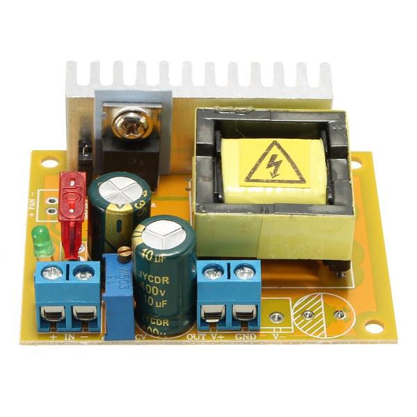
I've ordered a HV PS that claims to produce 40W continuous @100-240V, so I should have plenty of mA for both channels with it set for ~130V.

7a1500f5-b04d-4b80-89f4-2cc6157a0811.jpg

Actually an image of the 200-450V version, but the 100-240V version looks the same.

30 mA max plate current (5902)
x 4 tubes
+ ~6mA max plate current per plate (6021)
x 4 plates (2 tubes)
----------
144 mA max possible HV needs.

That should be less than half the rating of the PS. (~20 watts, counting losses)

I'll warm up some power resistors before I ever connect it to a tube.

Of course it is actually less dangerous than the PS in a conventional tube amp, but talking 20W @ 130V scares me, and this thing will do 40W@ 240V (70W peak for a short time). That's a serious bug zapper!

I also ordered a linear filament regulator with soft start.

I'm hoping to run the whole thing off of 12V, 4A power brick (on hand).

I am hoping the HV power supply only draws ~2A@12V when half loaded.

Filament calculations (6.3V filaments)
450 x 4 (5902)
285 x 2 (6021) (Each 6021 only has one set of heater connections)
--------
<2.5A @ 6.3V

= ~1.25A @ 12V (Assumes near 100% efficient linear regulator, which of course is not the case.)

Total current @12V = ~3.5A allows for less than 100% efficient power supplies, and still have some margin to run from a 4A power brick.
 
Just curious, what tubes are you planning to use for your outputs? You could go real cheap and use two 50C5's and a 12AX7 with the filaments in series and light them from the 115 VAC line in. This kind of thing was done all the time in the 60's. In fact, the 50C5 has a single ended power output of 2 watts and you could ditch the switching power supply altogether and just use a full wave bridge rectifier off of 115VAC line to get your 150v plate at 50 ma needed to run these. Then all you'd need to pony up for is a suitable output transformer.:)
 
OK, I put my money where my mouth is.

I am going to try this in a stereo power amp build using subminature tubes:
http://audiokarma.org/forums/index....re-p_p-amp-talk-me-out-of-building-it.847654/

I've ordered a HV PS that claims to produce 40W continuous @100-240V, so I should have plenty of mA for both channels with it set for ~130V.

7a1500f5-b04d-4b80-89f4-2cc6157a0811.jpg

Actually an image of the 200-450V version, but the 100-240V version looks the same.

30 mA max plate current (5902)
x 4 tubes
+ ~6mA max plate current per plate (6021)
x 4 plates (2 tubes)
----------
144 mA max possible HV needs.

That should be less than half the rating of the PS. (~20 watts, counting losses)

I'll warm up some power resistors before I ever connect it to a tube.

Of course it is actually less dangerous than the PS in a conventional tube amp, but talking 20W @ 130V scares me, and this thing will do 40W@ 240V (70W peak for a short time). That's a serious bug zapper!

I also ordered a linear filament regulator with soft start.

I'm hoping to run the whole thing off of 12V, 4A power brick (on hand).

I am hoping the HV power supply only draws ~2A@12V when half loaded.

Filament calculations (6.3V filaments)
450 x 4 (5902)
285 x 2 (6021) (Each 6021 only has one set of heater connections)
--------
<2.5A @ 6.3V

= ~1.25A @ 12V (Assumes near 100% efficient linear regulator, which of course is not the case.)

Total current @12V = ~3.5A allows for less than 100% efficient power supplies, and still have some margin to run from a 4A power brick.
This is very interesting.
I do think however that your 12V 4A supply may have problems with power-on surge. The tubes
will draw more at start. A 12V 8A smps might be needed, especially as both filament and B+ inverter
starts at the same time.

Keep us informed !
 
You want to go from 120v to 12v to 130v... Get a $2 power cord, $15 isolation tranny, two diodes, 2 caps, 2 resistors. Pick your own voltage.
Kind of said the same thing only I said just skip the isolation transformer and throw a full wave bridge rectifier on the 120VAC. It's isolated any way after you go through the output transformers:)
 
Back
Top Bottom