• The move to the new server is done. There are some software and database maintenance updates in process. This has us passing the hat around to help out. We appreciate any donations. Seriously, even a dollar helps. The payment page may be found here - https://www.audiokarma.org/support.html

Modern Power for Tube Projects?

So this thread seams to have "unwound" into a few separate topics.

Just in case anyone is actually reading this with consideration toward using some of the various units/modules to power a tube amp, I'll try to clarify some of the different sub-threads.

1. Using Chinese HV power supplies for B+ in a tube amp project. These run on a low voltage DC input, so discussion of AC line ("mains") isolation is not really relevant. I can say that the input is fused. The intended (nominal function) of these produce dangerous voltages and currents, so the safety of the output is not really relevant above and beyond normal tube amp high voltage precautions. I suppose input to output isolation could be a topic as far grounding/using multiple such modules in a single project. Discussion of output ripple (magnitude and frequency) is of course relevant.

2. Using buck converters for stable, (clean?) filament power. Again, These run on a low voltage DC input, so discussion of AC line ("mains") isolation is not really relevant. Bucks do not isolate input to output. I'm not denying that buck converters use switching to perform their function. I'm equally aware that they are used as a source of specific power inside a device (e.g. tube amp); however, at least in my mind, Switch Mode Power Supplies (SMPS) and buck converters are 2 different things. If it hasn't got an actual transformer, I call it a buck (or boost), and not a SMPS. Discussion of output ripple (magnitude and frequency) is of course just as relevant as said discussion for a SMPS. Discussion of switching frequency fields emanating from these devices is also relevant.

3. Using a positive/negative boost or buck converter to get a stable?, clean? negative bias voltage from a single and single-ended low voltage DC input. All comments from (2.) above are relevant.

4. Providing the DC low voltage input for all of the above. Yeah, I did mention cheap bricks, but for the discussion of 1., 2., 3., above, I think we should just assume that a safe, relatively clean source of LVDC, at sufficient current, is available.

It would also be more helpful if comments included specific modules/experiences. Repeating that "all Switch mode devices make bad stuff" is not really helpful. I think I can safely say that today there are devices (including those that produce sound) that successfully employ switch mode devices.
 
Yeah, I did mention cheap bricks, but for the discussion of 1., 2., 3., above, I think we should just assume that a safe, relatively clean source of LVDC, at sufficient current, is available. It would also be more helpful if comments included specific modules/experiences. Repeating that "all Switch mode devices make bad stuff" is not really helpful. I think I can safely say that today there are devices (including those that produce sound) that successfully employ switch mode devices.

What I wrote is that many SMPS, particularly those manufactured in China, cut corners to reduce costs, and that the noise can be prodigious and disruptive. LEDs are highly tolerant of such noise; tubes and audio, less so. I set forth an explanation of why snubbers would be required. I also explained, with specificity, why the proposed isolation transformer was a poor design.

My point was that engineering is more complex than was indicated by statements previously made by others, including yourself.

You clearly have your mind made up, no need to be confused with facts or the ramifications of poorly designed products from the real world.
 
I'm not disagreeing with you Rv, and the the "not really helpful" comment was not aimed at any one post or poster.

I've pried apart enough USB chargers, laptop chargers, etc. to have seen what you (and the referenced article) are talking about.

Yeah, I kinda do have my mind made up about using these Chinese modules to build another basic tube amp come h* or high water (the latter being a real possibility at the moment). My subminiature tube amp still works fine, does not buzz, and hasn't shot my tweeters across the room yet. Based on that, I am going to go forward with a 6BQ5 P-P amp based on similar Chinese modules.

Success or failure with this next project will likely be more determined by my available time, attention span, and basic construction abilities than the fact that it will use modules from China.
I think the idea is good. Do come back with your experience of the build.
 
... Practicing what I preach -- Keeping it to specific modules:

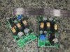
I have received the positive/negative buck boost supplies I intend to use to produce the "fixed" (in other words, not fixed at all, but really easily adjustable) bias.

IMG_20190910_pub.jpg


Out of the box, the one I powered up was set pretty close to +/- 15V, which should be the approximate bias for 6BQ5/EL84's with their cathodes hard tied to ground.

Actual voltage was like (meaning from memory) +14.97, and -15.02. As you can see, there is only one pot, but since there is no use in my project for the +15V, I will be setting the pot for proper average bias for the 4 tubes (both channels). I only intend to use 1 board for the whole (stereo P-P) amp.

I have not tested with a load, but it looks like they are plenty beefy for way more than is needed to bias a few grids. The boards are quite thick, and they are connected through so that most of the back is a heat sink. They are rated for 20W. (I wanna see the amp that uses 20W on it's grid bias!)

I was having difficulty measuring ripple. 1st, as mentioned, there was no load. It's pretty easy to filter ripple with no load, and 2.) I was getting 20mV of ripple on my un-grounded Fluke scope meter, in my test setup. This ripple was in the 10s of MHz, and was in everything, including the input power (which was from a linear bench supply). I think it may be from this PC that I am typing on now, which is quite close. Any ripple around any frequency that could be related to the switching frequency was orders of magnitude below that.

Note the small SMT capacitors bypassing the large electrolytics on the output, and how the ground pads are connected through to the back ground plane with lots of little plated-thru holes.

Again, not arguing with RV about how a lot of Chinese consumer electronics are made, but I don't see how these could be made better for what they are. I think there is a different ethic/priority for the Chinese companies that make such modules that are intended for projects/learning/development than there is for end-user consumer stuff. You can also see the width of the main current-carrying traces.

As mentioned, I did not connect a load, so I haven't checked load regulation. With the (-) output adjusted to exactly -15.00Vdc, there was no change at all in output with the input varied from +9Vdc to +20Vdc.
 
maybe use the +15v supply through a suitable dropper to run a power indicator LED or something. or use it to trigger the other supplies through a relay, if there is no bias then nothing else comes up.
 
I will be using a positive low voltage DC for something else in this amp. What this is will be revealed in the build thread, but you might guess that it is more Chinese modules. I think they will take +5V, not +15V, so there will be yet another small buck module. If the other modules will run on 15, then yes, I can use the (+) output of the bias module.

Don't worry about the other modules, this thing will still be pure tube in the signal path (after a possible built-in high-res DAC)

The pilot light will be probably be an old-fashioned neon light that is integral to the power switch.

I do like the idea about having the relay to not power the rest of the amp if there is no bias. It could also run a time delay to allow the heaters to be on for a time before the other power is applied. This would also help with problems trying to start all of these Switch mode devices at the same time. The way my Subminiature tube amp stalls the 12V brick during power up is not elegant.
 
I was having difficulty measuring ripple. 1st, as mentioned, there was no load. It's pretty easy to filter ripple with no load, and 2.) I was getting 20mV of ripple on my un-grounded Fluke scope meter, in my test setup. This ripple was in the 10s of MHz, and was in everything, including the input power (which was from a linear bench supply). I think it may be from this PC that I am typing on now, which is quite close. Any ripple around any frequency that could be related to the switching frequency was orders of magnitude below that. ... Again, not arguing with RV about how a lot of Chinese consumer electronics are made, but I don't see how these could be made better for what they are. ... As mentioned, I did not connect a load, so I haven't checked load regulation. With the (-) output adjusted to exactly -15.00Vdc, there was no change at all in output with the input varied from +9Vdc to +20Vdc.

I'm not trying to deprecate your project or decision. I've tried to explain the issues and will elaborate final time, then I'm done.

Not every SMPS is of equal quality. I have always maintained that the easiest and least-complex means to gauge power supply quality without any electrical measurements whatsoever is to simply weigh the two candidates in the hands and consider both the weight and number of components present. Any quality SMPS used for analog applications such as DACs, Class D, or high-performance audio amplifiers, will demonstrate considerably greater circuit complexity than the units you present.. You might consider why that is the case. The low component count in photo, and the emphasis on chokes and conventional aluminum electrolytics, provided suggests omission of filtering and regulating components, particularly for output regulation. Again, why would this be the case? A low-noise SMPS designed for analog applications has far greater complexity.

Your unloaded testing methodology in burst mode is insufficient to identify load-related issues, or to verify that artifacts from chopping are not present in the high tens to hundreds of kHz, or the low MHz. Identifying such frequency components can be difficult, even with the correct equipment.

Unlike a linear supply one may not merely throw capacitance at an SMPS as the spikes from charging current (c.f. conduction angle) may cause erratic supply behavior or to even result in a shut-down from a transient over-current condition. The electrolytic capacitors thrown at the problem will have a short lifespan prior to failure because of the ripple current, which is why any electrolytic in a SMPS must be low ESR, typically MLCC or tantalum. But that's a topic of its own.

Proper functioning for that unit may require an additional regulator with both a capacitance multiplier configuration. But that's no guarantee that one of those electrolytics won't go to Valhalla from the ripple current.

Ripple issues, noise, and load under regulation can become very tricky when the application is a high-bandwidth amplifier. The SMPS both (a) creates high-frequency switching artifacts and (b) poorly filters ripple current, mains harmonics, and mains noise from elsewhere in the environment. The switching artifacts may be readily amplified, as vacuum tubes have enormous bandwidth easily running into the tens of MHz. The fact that audio applications use tubes down near DC does not mean that the tube's bandwidth magically changes; this is why stopper resistors, in part, are used to ruin the Q of the circuits at higher frequencies. I don't see any manufacturer specifications for the SMPS performance on ripple, HF components, noise, RF emissions, etc. I doubt the vendor even has such data. Given the lack of circuitry on that board, I would expect that undesirable frequency components are present and will be received by every wire and long lead in the amplifier. Rejection of mains noise by the SMPS is poor, so every noisy SMPS in your home is going to pump HF noise into your device.

It is easy to fabricate a tube amplifier which basically works most of the time. It is far more difficult to design a tube amplifier which is low-noise, stable (free of ringing and oscillation), able to drive a capacitive load, and which does not waste power on signal (ripple, noise, or switching artifacts) out of the audio band. The SMPS is similar. Designing a low-cost SMPS that sort of works is trivial, but the performance will suffer. Designing a high-performance SMPS is difficult.

I'm not saying that an SMPS is a bad idea for audio. I'm saying that you don't know this particular unit is the best choice. If it causes poor amplifier performance, or, worse yet, takes out a quad of expensive output tubes have you really saved any money?

One caution: if a fixed-bias supply fails the amplifer chernobyls. Using a relay to interrupt the B+ in the event of bias failure is not viable because high voltage will arc across the contacts. Interrupting B+ requires a high-voltage MOSFET or an equivalent. Conversely, using a mechanical relay to enable B+ will result in contacts which are pitted and maybe even spot-welded at some point. A solid-state device is required.
 
I was thinking use the bias supply + side to relay the input to the HV boost converter. Switching the <20v input would be much less difficult than breaking ~300vdc.
 
I was thinking use the bias supply + side to relay the input to the HV boost converter. Switching the <20v input would be much less difficult than breaking ~300vdc.

That would work.

You'd written, "...or use it to trigger the other supplies through a relay, if there is no bias then nothing else comes up." so I thought your proposal was to switch B+.

The bigger concern is the design issues with the supplies. Plus protection in case the bias supply fails.
 
'Never considered putting the relay in the HV B+ output. The relay would kill the 12V power upstream of both the Plate supply, and the supply for the screen and the 12AX7's.

The NC relay contacts could run a big, fat "Failure" LED.

I realized (based on gadget73's comment) that a bias failure would not be good. As mentioned, a single one of these HV supply modules is rated at 70 - 100W (That's operation -- I have no idea what it takes to shut it down) and the new, bigger OPT's I bought are still only rated at 20W, so with no (-) bias, it is probably well capable of killing the OPT's and tubes. (I'll have 4 warning lights if it happens!)

Fuses, or sacrificial, low value resistors on the cathodes are also in the plan. (I currently have 1 ohm resistors drawn in there -- have to do some maths for the wattage rating).
I get that it may be difficult to get a rating that won't get hot/fail over time with normal use, but open if there is a loss of bias.

Running fixed (-), (grid) bias is only based on a philosophical point about hard-grounding the cathodes. If I'm going to add complexity/failure modes/cost/etc. that really does not buy anything, I may not do it.

On the other hand, as mentioned, these (-) boost modules look way over-rated for the power they will supply to a few grids. Given what is at stake (fairly cheap OPT's, and a few Russian 6BQ5's), the risk/consequence chart probably says "Go for it, and don't worry about a grid bias failure."

The answer would be different if I were running 8 matched 6L6's per channel and the appropriate custom OPT's. (Not that I would ever think of building an amp like that or anything :rolleyes:)

As far as the weight when you hold them in your hand -- Yeah -- The 12V (input) power supply that I am currently using for the subminiature tube amp feels like an empty plastic box when you pick it up. It's the one that stalls on start up. It's rated at 6A, but a much heavier one (exactly the same size) that is rated at 4A does not stall on startup -- go figure.

Again, a PC speaker amp is not exactly a critical operation.

For the Input (12V) PS, I may order a better quality power supply chassis that I can build into the amp's chassis.
 
Fuses, or sacrificial, low value resistors on the cathodes are also in the plan. (I currently have 1 ohm resistors drawn in there -- have to do some maths for the wattage rating).
I get that it may be difficult to get a rating that won't get hot/fail over time with normal use, but open if there is a loss of bias.

Resistors are not fuses, and many resistors will happily tolerate considerable overload for hours or days before blowing. Long past the point that the rest of the amplifier has burned through the basement on its long journey back to China.

On the other hand, as mentioned, these (-) boost modules look way over-rated for the power they will supply to a few grids. Given what is at stake (fairly cheap OPT's, and a few Russian 6BQ5's), the risk/consequence chart probably says "Go for it, and don't worry about a grid bias failure."

An underloaded SMPS often not properly regulate. You may need to add a dummy load.

As far as the weight when you hold them in your hand -- Yeah -- The 12V (input) power supply that I am currently using for the subminiature tube amp feels like an empty plastic box when you pick it up. It's the one that stalls on start up. It's rated at 6A, but a much heavier one (exactly the same size) that is rated at 4A does not stall on startup -- go figure.

The design of those supplies is problematic enough that generalizing between different units from different manufacturers is likely not possible.

Again, a PC speaker amp is not exactly a critical operation.

I always say that if one treats every project as a learning experience over time one's skills grow. Reducing projects to barely adequate is likely not a good process to inculcate first-rate design as per best practices as a routine practice.
 
Lots O' Chinese SMPS Modules!

rps20190919_091847.jpg

Note that the 2 on the right are not the same as the similar looking one on the left.

The one on the left is 100 - 250V, and the same as the one used in my subminiature tube amp. The ones on the right are 250 - 400V, and one of these will be the 320V source for my next project.

Center lower is a combination filament and HV supply. More on that unit after I have played with it on the bench.
 
Those are rated at 70 watts. Some vendors seem to say 70-100W for the same modules.

So ~200ma at a typical B+ voltage setting for a small power amp. I wouldn't recommend running them near the max voltage. The output filter cap is only rated at 450V.
 
ElPaso TubeAmps has a you tube video showing one of these running 448 volts and 40 watts continuous output.


The manufacturer says 40 watts continuous and 70 watts peak.

Steve
 
Yup, that's the same PS module.

Thanks, Steve for linking that here, and thanks to the guy from ElPaso TubeAmps for a cool video.

I have not tested the ~450V ones that I have yet, but there is data previously in this thread for the ~250V version of the same PS.

A couple notes:

-- Too bad he did not hook up a scope and check the ripple at that voltage/load.
-- I don't agree that it replaces everything on the tube PS chassis. Since this PS runs on 12V input, you need a 110V-12V power supply to really make the equivalent of a typical Tube PS.
-- I strongly recommend against using these at a voltage setting near the upper limit. The final cap is only rated at 450V. Running them at 448V like he is showing is asking for an explosion or some other sort of unpleasantness sooner or latter. My intended B+ is ~320V, so I have at least some margin. For the ~$13, they do not include hearing or eye protection, a breathing filter, or a mini vacuum cleaner to clean up the mess from an exploded electrolytic. (I suppose replacing the final filter cap is a cheaper alternative.)

EDIT: My evaluation of the 250V version of the above mentioned power supply is not in this thread. It is in my Submini Tube Amp Project Thread, starting here:
https://audiokarma.org/forums/index...ut-of-building-it.847654/page-2#post-12248483


I have some data on the other power supplies (the lower wattage ones that have both filament and HV sections), but I will hold off on that so as not to cause confusion about which PS we are talking about.
 
Last edited:
Here is a quick review of a different PS module:

IMG_20190918_203506_sm.jpg

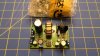
This module actually has 2 sections:

1.) An LM2576 based Buck converter. This is the bottom section as shown in the above picture. It is intended as a filament supply.
2.) An TL-494-based Boost converter. This is the rest of the board, including the MOSFET in the heat sink, the large coil, and the large capacitor at the upper left. It is intended for a HV supply, and is advertised as 100-420V.

One good thing about this particular module is that the vendor provided a schematic in the ad. (no documentation comes with any of these modules when you actually get them.)

schematic_sm.jpg

In the case of the schematic, the low voltage PS is at the top, and the HV PS is at the bottom. Both sides run from a single 12VDC input.

I set up the Low Voltage side for 6.1Volts, and attached an automotive halogen light bulb as a load. The LM2576 is rated at 3A max, and one filament of the bulb was about 2.9A. Regulation was not as good as I expected. The voltage sagged by about 0.2V from no load to full load (which really is not that bad, and part of that is from test leads, and the shunt in the meter I was using to measure current). With the no load set voltage at 6.3V, I got the 6.1V I wanted. The LM2576 got very hot very quickly at full load.

123_Screen3.png

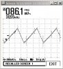
Here is a Fluke Scope meter shot at ~3A load. About 0.3V p-p of ripple, with most of it at 30KHz. I'm not really sure what one would expect with this sort of ripple on the heater voltage. I guess that in P-P, anything that did get in via the filaments should cancel. Also, some of this could be due to the test set up (long test leads, etc.), but I was expecting better. .3V ripple on a 6V power supply (as Shania Twain says) "...Don't impress me much."

I didn't actually record it, but with no load, the ripple was in the few mV range.

Worse than that, the Amp I want to build needs about 3.6A total filament current. While this would probably source that much on the bench, and a small heat sink on the LM2576 would help, I am not sure it would last at that current.

I think this module would probably work fine for the heater demand of a small pre-amp. Perhaps one or two 12AU7/12AX7, but in my case, I think I'm going to need something beefier. Splitting up the loads is another possible solution.

I have a buck rated at 5A, and another rated at 6A, so I will test them.

Perhaps I will still use this module, but set the Low Voltage to 5V for some "other features" I have planned for this amp.

I don't have a proper load for the HV section, so I only tested open circuit. The low voltage section was un-loaded when checking the HV section.

123_Screen4.png

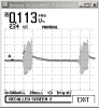
This is the un-loaded output of the HV side with it set for 280V. It has these interesting bursts a a very low frequency. Again, this could be my test setup. I am using direct probes, as I do not have the special adapter to use a x10 prove with my Fluke. Other than that, it looks very quiet, and there is no change in output, even with "gross" changes in the input voltage (I tried 10V-15V.)

For my planned project, I am (pure guess) planning for well under 50mA on the 280V power supply. Again, I would think it would be fine as long as those bursts are not there with a load.

To pull 50mA @ 280V, I need a 5.6K resistor that can handle the power at least long enough to test.

Note also that there is a 3rd pot. The pot near the heat sink allows you to adjust the max current, but without a suitable load, I was not able to test that.

Again, for my planned project, B+ (320 - 380V) will come from the 450V module mentioned in the other posts, not from one of these.
 
Last edited:
Here is a quick review of a different PS module:

View attachment 1626111

This module actually has 2 sections:

1.) An LM2576 based Buck converter. This is the bottom section as shown in the above picture. It is intended as a filament supply.
2.) An TL-494-based Boost converter. This is the rest of the board, including the MOSFET in the heat sink, the large coil, and the large capacitor at the upper left. It is intended for a HV supply, and is advertised as 100-420V.

One good thing about this particular module is that the vendor provided a schematic in the ad. (no documentation comes with any of these modules when you actually get them.)

View attachment 1626114

In the case of the schematic, the low voltage PS is at the top, and the HV PS is at the bottom. Both sides run from a single 12VDC input.

I set up the Low Voltage side for 6.1Volts, and attached an automotive halogen light bulb as a load. The LM2576 is rated at 3A max, and one filament of the bulb was about 2.9A. Regulation was not as good as I expected. The voltage sagged by about 0.2V from no load to full load (which really is not that bad, and part of that is from test leads, and the shunt in the meter I was using to measure current). With the no load set voltage at 6.3V, I got the 6.1V I wanted. The LM2576 got very hot very quickly at full load.

View attachment 1626118

Here is a Fluke Scope meter shot at ~3A load. About 0.3V p-p of ripple, with most of it at 30KHz. I'm not really sure what one would expect with this sort of ripple on the heater voltage. I guess that in P-P, anything that did get in via the filaments should cancel. Also, some of this could be due to the test set up (long test leads, etc.), but I was expecting better. .3V ripple on a 6V power supply (as Shania Twain says) "...Don't impress me much."

I didn't actually record it, but with no load, the ripple was in the few mV range.

Worse than that, the Amp I want to build needs about 3.6A total filament current. While this would probably source that much on the bench, and a small heat sink on the LM2576 would help, I am not sure it would last at that current.

I think this module would probably work fine for the heater demand of a small pre-amp. Perhaps one or two 12AU7/12AX7, but in my case, I think I'm going to need something beefier. Splitting up the loads is another possible solution.

I have a buck rated at 5A, and another rated at 6A, so I will test them.

Perhaps I will still use this module, but set the Low Voltage to 5V for some "other features" I have planned for this amp.

I don't have a proper load for the HV section, so I only tested open circuit. The low voltage section was un-loaded when checking the HV section.

View attachment 1626159

This is the un-loaded output of the HV side with it set for 280V. It has these interesting bursts a a very low frequency. Again, this could be my test setup. I am using direct probes, as I do not have the special adapter to use a x10 prove with my Fluke. Other than that, it looks very quiet, and there is no change in output, even with "gross" changes in the input voltage (I tried 10V-15V.)

For my planned project, I am (pure guess) planning for well under 50mA on the 280V power supply. Again, I would think it would be fine as long as those bursts are not there with a load.

To pull 50mA @ 280V, I need a 5.6K resistor that can handle the power at least long enough to test.

Note also that there is a 3rd pot. The pot near the heat sink allows you to adjust the max current, but without a suitable load, I was not able to test that.

Again, for my planned project, B+ (320 - 380V) will come from the 450V module mentioned in the other posts, not from one of these.
Where did you find this one ?
 
Where did you find this one ?

I have been buying all of these from various vendors on "that popular auction site".

To find these, you have to be kinda creative with your search terms as many China-based vendors do not title thier auctions using the ideal words for a logical search.
 
I have been buying all of these from various vendors on "that popular auction site".

To find these, you have to be kinda creative with your search terms as many China-based vendors do not title thier auctions using the ideal words for a logical search.
Ok. What item number does it have ?
 
Back
Top Bottom