• The move to the new server is done. There are some software and database maintenance updates in process. This has us passing the hat around to help out. We appreciate any donations. Seriously, even a dollar helps. The payment page may be found here - https://www.audiokarma.org/support.html

Modern Power for Tube Projects?

switchers can be clean. The supply I used to use for DC radio gear is absolutely silent. I've sniffed it with the scope and with shortwave radios, never found a noise spike. The lights in the shop are a different story entirely. The filter banks in my 40a supply are a whole lot more extensive than I expect the $25 shop light ballast has.

They can be, but very few switchers are clean. Many are very dirty.
 
More hardware...

... Shipped directly from the Wuhan wet markets...

..has arrived (actually, they are from Shenzhen, but I'm not sure that makes much difference. )


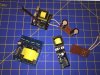
Inverters_China.jpg


As mentioned, these are the inverter supplies. They are essentially exactly what is needed for a simple, inexpensive tube power supply except for the secondary components (Rectifier, filter, and optionally feedback.)

Note that the one in the center, and the one at the top are almost identical circuitry, just a different form factor.

As you can see, I quickly made up a few rectifiers with the high speed glass diodes I bought.

What they are doing here is basically running a SG3525 PWM chip open loop. There's no regulation or voltage adjustment.

There are different taps on the secondary of the transformer, although not all pins are connected. V0 -to- V5 on the smaller units is 220VAC. There is nothing connected to the hole marked V1.

Even using the last tap on the smaller supply, I didn't get as much voltage as I would have liked to, so I tried the shown voltage doubler. On the 2nd (real) tap, as shown I get about 380V no-load, and about 350V with load. Connecting to a higher tap would result in "unpleasant things" happening to the shown 100µF/400V capacitors.

In working with these things last night, nothing got even slightly warm except the load resistor I was using. Attempting to continue to use the (was blue, now brown) resistor I was using will very likely result in a fire. While I can't leave the power supply running very long due to lack of a suitable load, at one point, it was supplying 170ma at ~350V, without even appearing to struggle at all.

At one point in my efforts to cook power resistors, my 6A Military grade lab PS dropped out of regulation (Supplying about 5.25A), and even in this case, the MOSFETS on the shown inverter board only got barely warm.

Input (12VDC) current was 1.3A, running at 350V/50ma output.

Note that the other small unit has no heat sinks on the MOSFETs. From what I have seen, and for the intended use, they are probably not even needed.

Also, with the capacitors shown, ripple was very low -- yes, there was all sorts of high frequency hash, but it (at least as far as my scope meter could measure) was down in the mV's. I have some tricks for dealing with even that, too. I intend to place a 0.1µF/650V cap in parallel on the output, and I have some inductors removed from "real" SMPS's.

I'm trying to learn more about the SG3525. If I could either actually make them work as a regulated power supply, or at least adjust the duty cycle in order to get the exact voltage I want, that would achieve the goal of this whole effort. If not, I'll probably go with the 220VAC tap, and the bridge, and take what I get. (That is also the most efficient configuration.)

One last note -- Cheating is also possible -- With the voltage doubler connected as shown, it was easy to get exactly 320V under load by adjusting the 12VDC supply voltage down to ~11V. So adding a DC - DC buck of sufficient ratings between the 12V source supply and the shown inverters would get me exactly what I want, but like I say, that is "cheating".

These things are *so* close to what I have been talking about all along. I have no idea why someone over there in Shenzhen doesn't supply one with the rest of the work done.
 
could always liquid cool the resistor. Just drop it in a cup of water. The resistance through the water shouldn't be low enough to significantly affect total value, but it will suck the heat away right nicely.
 
Just drop it in a cup of water.

I have particularly conductive tap water where I live. It added enough current to make my PS (the lab PS) go into current protection, and it also rusted my alligator clips. Perhaps distilled water.

I successfully modified the smaller inverter so that I could adjust the duty cycle, and thus the voltage. All it took was a 10K pot, and a 100K feedback resistor from pin 9 of the SG3525.

The problem I'm having now is a tremendous voltage drop from no-load to full load.

For the voltage doubler connected as show, and set for 320V under full load, it's 380V no-load. I think most of the voltage drop is happening in the small windings of the transformer.

I think I'm going to try actual feedback voltage regulation. At least I'll learn a little more about SMPS's.

The other path is to actually hook up the smaller power supply to the amp, and see what the actual voltage drop is from cold tubes to actual operation.
 
@linuxslate et al: 'Great thread! I'm just getting back into tubes; pre-retirement E.E.; rusty from years wasted in I.T. ;-) ...I've been noodling on the exact same thought-experiment (lacking the research/experimentation shown over your last several weeks). I appreciate the safety and interference caveats, but similarly cannot avoid the lure of smaller, cheaper, higher-efficiency DC creation.
I wish you well on your quest, and look forward to posts, as viewers might anticipate a next episode of a serial Mexican Soap-Opera :lurk:
 
deionized would be better, but I' surprised its conductive enough to cause trouble. Unless it soaked into the resistor and messed up the value that way. I have a large pool of DI water at work. The way we used to light it was to drop 120v 300w halogen flood lamps with the glass removed into the pool. All electrical connections completely immersed, and it wouldn't trip anything when plugged straight into the outlet. All depends on the conductivity of the water.
 
...I wish you well on your quest, and look forward to posts, as viewers might anticipate a next episode of a serial Mexican Soap-Opera :lurk:

Soap-Opera, Mess. I'll admit it that buying a $10 Chinese module, and dropping it in a full power tube amp didn't work. (I still maintain that it did work for my subminature flea power amp.) I really, and non-sarcastically appreciate the naysayers. If it weren't for them, I probably would have given up. The "something to prove" has kept me going.

I should also point out that with all of the modules I have bought (and there is still one more coming), I don't think I have spent any more than a decent custom made "normal" (60Hz) transformer would have cost me. There's no reason I can't drop one in the bottom of this chassis.

At any rate, here is the next episode of the soap-opera (or perhaps a sit-com):


Before I start, I need to mention a few notes about my test environment. First, this is Florida, and we are already having warm weather. Plus a little from the lights, soldering iron, etc. The IR thermometer shows the table over 80 F. before I even start.

Second, it's noisy in here. -- Far from a quiet listening room. I'm very close to a fish tank that makes all sorts of pump vibration and gurgling water noises. The air handler is also right next to my bench.


I've basically made a regulated voltage doubler supply out of one of the smaller inverter modules. Output is about 324V at no-load, and around 314V (lowest setting) once the tubes start conducting.

It works, and it will run for hours, but it gets noisy after about the first 5 - 15 minutes. For one song, it's someplace between dead quiet, and acceptable for an experimental amp. After about 15 minutes, it slowly develops something similar to a 60hz hum, but ... Different. As an instructor used to say, it's "Rich in Frequencies" ("Rrrreech en Fleeckwencies" as he said it). I mention the noisy environment because I have the even "hot" noise down to the point where between the fish tank and the AC, it's "almost acceptable". It's not low enough, however to call success, or for normal listening.

I've also made a larger heatsink and used insulators to attach the MOSFETs. It gets quite hot, and I think the MOSFETs may be causing noise/instability when they get hot.

Here's a hand-drawn schematic of my additions/changes to the Inverter Module. Sorry for the poor quality. Obviously, only the secondary, and the changes around the IC's are shown. The MOSFETs and the rest of the circuitry to make the SG3525 work are not shown, nor are they changed.

VoltDoubler.jpg

Note that the current FB resistor values were selected for 320V. The minimum I can set it to right now is ~314V under load. Changing the (2) 300K resistors to 270K should let me select a lower voltage. This will result in lower watts, and lower MOSFET duty cycle, which should help a lot with the heat.

To give credit where credit is due, this is largely from Tahmid's blog. Note that he builds a 290V supply, which is nearly what I am trying to do, but as with the others, he winds a custom transformer.

Right now, the whole thing is just sitting on the back of the amp, using a CD jewel case to insulate it from the chassis. Once I am closer to something that is acceptable, I will re-build it in a manner that allows it to be mounted to the chassis.
 
can you hang a scope on the output of the supply to see what its doing when you get noise in the output? If altering the supply voltage doesn't sort it, perhaps adding some filtering of the right flavor will.
 
Just a quick update...

I changed the shown 300K resistors to 270K, and now I get voltages in the 270 - 290 range (with load -- Sorry, did not record the actual voltage range). They seem to adjust "more nicely" when I turn the pot, too.

It still gets noisy after about 15min worth of use but it takes longer, and after about an hour of use it couldn't be heard a few feet from the speakers and with the AC running.

Now I'm not sure if this (plate) supply is getting noisy when it gets hot, or if it is the main +12VDC supply, or something else. If I'm reducing the wattage drawn by the plate supply, I am also reducing the load on the +12VDC supply, so it could still be either one.

Unfortunately, due to the current world situation, I can't rummage through the bins at my local surplus place for heatsinks.

As I was just typing this, a neuron fired, and I realized I can bend bits of aluminum to get myself a lot more area, and possibly a mounting bracket at the same time. For some reason my brain didn't realize that you can bend aluminum angle if you make some strategic cuts first. Probably be Saturday until I can try that.

@gadget73 : I'll upload some screen shots.
 
Here's some good pictures that show what is happening as it warms up.

This is set to look at the low frequency components that are causing the audible noise. The high frequency hash is probably not getting through enough to appear on the speaker terminals.

This is the output of the HV (plate) power supply, AC coupled.

There are 3 wave forms attached.
The first is just after the tubes have warmed up and are conducting (about a minute or two after power up.)
The second is just as the low frequency becomes audible.
The third is after the amp has been idling about 15 minutes. I don't think it gets much worse than this.
(The times are obviously not accurate -- I guess my Windows Emulator doesn't know what time it is, but the relative times should be accurate. Maybe the scope doesn't know what time it is.)

I need to check the ripple on the input to the HV power supply. I don't think it develops the same thing, but I need to check again.

BTW, this is the first time I've used the Fluke Scopeview software to capture the waveform like this (as opposed to a screen shot of the scope). It's easier, and produces a much better product.
 

Attachments

  • Low_Freq_Cold.jpg
    Low_Freq_Cold.jpg
    60 KB · Views: 8
  • Low_Freq_Warm.jpg
    Low_Freq_Warm.jpg
    59.6 KB · Views: 6
  • Low_Freq_Warm2.jpg
    Low_Freq_Warm2.jpg
    63.2 KB · Views: 6
HF hash can probably be sorted with a film cap across the output and maybe a small value choke in series. The ripple though, looks like ~60 hz? Not sure where that would be coming from if its all SMPS if its not coming through on the main input. Quick and dirty test, if the initial input is 12v, connect it to a battery and completely eliminate any connection to the mains. If that makes the 60hz hum go away, then it has to be something related to the supply thats actually plugged in to the wall.

unless I've just gotten lost on what the basic supply diagram is at this point, which is entirely likely. If I'm lost, could you knock together a basic block diagram showing what goes where and how they tie together?
 
The schematic remains basically the same. The power tube heaters are still running from the buck. I haven't re-wired them yet.

See the 2nd attachment in this post:
https://audiokarma.org/forums/index...ower-el84-p-p-amp.889877/page-2#post-13521945

The only difference is that the relay coil now runs from the + side of the +/- 15V bias supply.

There is also a small value choke between the 2nd diode of the multiplier and the last filter cap. (It was there when I captured the above wave forms.) The regulation feedback is taken after the choke. It's appropriately heavy wire on an inch long pencil size ferrite rod, so only about a dozen turns. It's from a scrapped "real" SMPS.

I also do plan to put a 0.1µF 650V chiclet in parallel with the last filter cap for the real built. That is not there right now. I think the chiclets are film capacitors.

--------

I made a new, and much larger heatsink/mounting bracket. It's still trying, but it's having difficulty getting this heatsink as hot. It's been running for 20minutes, and the hum is not audible 3 ft away with the Airconditioner running. Definitely not near as bad as when I captured the 3rd wave form in my previous post.

The heatsink/bracket is not attached to the chassis at this time. It's sill sitting on top of the CD jewel case.

I get that if it is really 60Hz, it has to be (most likely) from the PS that is connected to the AC Line, but it is not a stable frequency. Not on the scopemeter, or audibly. The captures above can't show that. Also, There definitely seems to be correlation between the temperature of the Plate Supply MOSFETS and the hum.

------

I just made is so that I can run the plate supply from my bench power supply, and the rest is running from the internal 12VDC supply...

Edit: (Returns connected, of course.)

Now I have to listen to music for an hour again. Testing tube amps is tough work.
 
Last edited:
Over an hour now running with the plate supply powered from my bench power supply, and the rest running from the internal 12VDC supply.

No increase in hum/buzz from just after startup. @gadget73 was right. The 60Hz (low frequency stuff) has to be coming from the main supply.

There is still a ear-to-speaker "spooky old person moaning or mumbling", and still a very low hum/buzz, but this is, IMHO, acceptable.

Sitting in my chair 2 ft from the speakers, The fish tank pump in the next room, clothes dryer past closed door, and now my bench power supply fan all (each) drown out anything coming from the speakers with the amp idle.

When I ordered the 12VDC supply, I ordered and received 2, but I can't find the other one right now.

I'm looking on "a certain popular auction site" for better quality 12VDC power supplies that are rated at 8A or greater, and will fit.
 
happen to have a decent capacity 12v battery around? just curious if that would completely shut it up.

chicklet caps are some flavor of film. If you've got a choke in there, stick one cap on each side of it to ground to form a pi filter. That will filter HF hash more effectively than just a single.
 
happen to have a decent capacity 12v battery around?

Chuckle -- We fly R/C planes, including some fairly large Electric Jets (EDF). Some run 100's of watts. (I seem to be into anything that is incredibly electrically inefficient.)

So yeah soldering on a couple of XT60 connectors did cross my mind, but I'm not sure what that would prove.

The moaning in the wind is from the high frequency switching of the plate supply itself, and the low frequency stuff is from the main PS. Somehow it's passing low frequency stuff as it gets hot.

Thinking of that 12VDC 8A power supply ---

1. It's one of those cheap "LED" power supplies. Just looking through the holes, one can see a lot of un-populated places for parts on the PC board. I can even see jumpers where there is an outline of a choke. Callouts for Cx where there is no capacitor, etc. I think they take a decently designed SMPS, leave off half the parts, and sell it as a lighting power supply.

2. It's running near it's max rated power 3A plate supply, 2A screen supply, 4 power tube heaters (call it 2A reflected on the 12V PS), 300ma + any program (Music) power. An estimate of 7.5A leaves some room for program power, but leaves no room for a Chines power supply advertised at 8A.

3. It's in a really bad environment. It's probably 120 - 150 Deg F in there.

The chassis has large cooling slots on both sides to let air in, To build the amp itself, I swapped the upper and lower plates of the chassis. So there are also plenty of slots for air to enter the bottom, but there is no way for it to exit the top. No real convective flow.

I don't think what I am asking the 12V power supply to do (Including any possible replacement) is really reasonable.

There are small holes near the power tubes for a little convection cooling, but they are completely insufficient for any real flow through the chassis.

There's not much room for holes, and I can't really cut slots. Any significant holes in the top will allow dust/debris in, and of course there are also aesthetic considerations to how and were to drill holes.

Never the less, I think it needs some convection exit flow. I'm looking at the amp, and figuring out how/where I can drill some holes -- perhaps a row between the OPT's, and a few more closer to the front.

I can drill more small holes, or fewer larger holes. Perhaps large holes covered with metal mesh.

The whole, assembled thing (less tubes, of course) is going back under the drill press.

Edit: Yes, I'll dump the filings out of the PS before I turn it on again.
 
Update:

Since this is really about this particular amp, it should be in the other thread.

I drilled (14) 1/4 inch holes in the top.

I really think I notice a significant difference. I think I can feel hot air coming out of the holes, and after running for quite a while earlier, the sides of the chassis felt considerably cooler than they had before. I think that is because there is airflow going in the slots instead of just stagnant air.

Yeah, after an hour it had both the moaning in the wind, and the hum, but it remained pretty low. I think I'm going to call it acceptable for an experimental amp.

Since it was working so well, I decided to destroy the secondary circuit I made. I re-built it in a configuration for permanent mounting. It now has a .1µF 650V cap across the output, but it no longer has the choke. There isn't room for the choke, let alone a pi configuration filter.

I actually put a lot of hours into it today, but between the current world situation, and rain, there really wasn't much else I could do. It's late now, but it's up and running again.

I have to keep it very low right now, but I'm streaming TranceBase.FM again, and even with it this low (16%) the hum is not objectionable. It's really only noticeable when the announcer speaks. (I can't understand him, but that's actually more due the fact that he is speaking Dutch.)

I think I'm done for now. If I ever come across other HV modules, I may try them, but for now, I am going to attach the HV power supply to the chassis, build the Lexan protection, and call it a completed project.

I also need to do a final check of Screen voltage, bias, etc.

Pictures will be posted in the other thread soon, (probably less the Lexan cage.)
 
Just a quick picture of the Plate Supply in it's "final" form (at least until it blows up).

Plate_Supply.jpg

The Terminals on the right are -- top to bottom -- 2 outputs (center taps of each OPT), Ground, and +12VDC (red mark).

I'm back to the garbage can metal mesh for covering it since it will provide better cooling, and is very easy to cut/mount on the top of the heatsink. A standoff in the hole at the lower right will support the cover on that side.

I've also had a significant discovery with respect to the low frequency hum. Once it starts, it can be reduced, and sometimes stopped almost completely by knocking or tapping the chassis.

In other words, the whole hum issue seems to be just a poor connection.
 
Pictures posted in the build thread for the particular amp I have been trying to build.

I'll keep this thread going, and I would appreciate others posting, for relevant SMPS information for tube amps -- pre-amps, flea power amps, and full-on power amps, but please specify what you are taking about.

I promise to up my standards, and stop filling AK's hard drives with stuff about $5 Chinese modules that are not up to the task of running audio equipment.

Thanks very much to all who posted in both these threads, I could not have gotten this far without both the help and naysayers.
 
Bumping a thread again that mostly consists of me talking to myself; However, there is some interest in other threads (not just my threads) about using SMPS's in tube projects, and I do have some news, so as promised I'm going to update this thread.

1:

An update on my 2 SMPS amps I've already built: My sub-mini tube PP PC Speaker amp has been running just short of 2 years. I upgraded my PC monitor to one that does not have built in speakers, so the sub-mini tube amp is the only way I get sound from my PC. This means it is powered up and down many times a day, and/or left running almost continuously. I frequently forget to power it off, so it sometimes runs overnight, or while I am away. I still have a house. It is absolutely dead silent when the PC is not playing a sound.

It has been over 6 months since I built my "Modern Power" 6BQ5 PP amp. It does not get nearly as much use, but there have been several times where I have used it for >3 hours at a time. We haven't really gotten any cool temps here in central Florida in the last 6 months, so when it is used, it is always with an ambient temp near 80°F. Yes, it still makes a very slight "moaning in the wind" sound when idle, but it is generally not noticeable with even low volume, or lulls in the music.

2:

I'm at it again -- This time even larger. I'm rebuilding a Rowe R-3459 Juke Box amp. I'm going to convert it to 7591's, and --- Yes, I'm seriously thinking of using an SMPS.

I've just gotten addicted to some of the features an SMPS enables, such as:
  1. Low weight
  2. Flexibility in locating PS components
  3. Regulated output for both B+ and heater voltages
  4. Wide supply range without changing taps or switches: 100-240VAC, and they would run on DC as well
AFAIK, the Power Transformer in the Rowe is fine, and I may still decided to stick with linear, but as of right now, I am planning on doing one of the following:

Either building my own rectifier/filter/divider based on the larger unit (lower left) in this picture:
index.php

I have some very good high speed, high voltage, high current diodes that would be fine. The only thing I don't have is a suitable load for bench testing. (3 light bulbs in series?)

If I build a PS using the large inverter pictured, I will not use separate modules for the screen and driver/PI stages. I will use a conventional resistor/capacitor ladder to get the correct voltages and filtering. I will either run all of the heaters in pairs from the 12V supply, or I will use a separate buck for the 7591 heaters.

I'll need almost 15A (total) at 12VDC, but an Xbox power supply is rated at >17A @ 12VDC, and I have fond several of them at very reasonable prices at thrift stores. One of them will get naked, and go inside the chassis.

I have ruled out using the "Moving Head" Lighting power supply due to the fact that it is not isolated. It's not so much a safety issue (although that is part of it) it's just that there is no easy way to set up an input ground reference using that power supply. I could use an isolation transformer, but that kinda ruins much of the point.

See below for another alternative:

3:

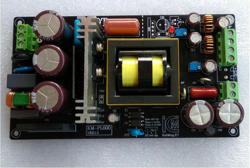
I continue to research SMSP's with appropriate output voltage for a full power PP Tube amp --- And --- There actually are some:

s-l1600.jpg

(Ebay image link -- no vendor shown or mentioned -- link will expire at some point)

This unit runs from 200-240 VAC input, and provides DC200V-520V as the main (Plate) output as well as several DC voltages for heaters, and a (-) DC for bias.

It is fully isolated, even to the point of using optical isolators for the feedback.

The B+ is customizable when you order, but not adjustable. I need to contact the vendor, and see if they have or can make a version for US line voltages.

It's rated at 300W continuous, which is nearly twice my power budget for even a PP 7591 amp.

There is another similar unit rated at 150W (total), and with a 95-265 VAC input. It's HV (B+) is rated for 300ma (max) which is not enough for a "big bottle" PP amp, but it may be adequate for a smaller PP amp, or a SE 6BQ5 setup. It also has a 6.3V output for heaters.

There's an even smaller version rated at 60W, which is probably only appropriate for preamps. It has the same 95-265 VAC input, and is really small. These last 2 are also isolated.

 
Back
Top Bottom