• The move to the new server is done. There are some software and database maintenance updates in process. This has us passing the hat around to help out. We appreciate any donations. Seriously, even a dollar helps. The payment page may be found here - https://www.audiokarma.org/support.html

Modern Power for Tube Projects?

Thanks for posting.
The only time I've used a switched supply was in a box to burn in foil capacitors, with DC high voltage applied to the caps, and white noise generator to get some current through.
That supply was emitting so much noise that it would have been unusable in an audio amplifier.
I hope the one you have is not as noisy as mine.
 
Well done for persevering for 2 years on this general topic.

I have enjoyed adapting a few ebay modules for valve amp use, and generally found them quite nice as far as smps go. I certainly recommend using a commercial approved mains to 12VDC power supply (brick or plugpack or whatever), just as long as it is safety approved and has sufficient output current rating.

I would also recommend aiming to use the 12VDC feed for heater powering, and trying to use any scheme that doesn't need a separate heater smps. That may introduce some compromises, like needing to use 6V heater tubes in pairs, and so may not be great for SE amps, but well worth trying to keep it simple for starters. For lower powered amps, that use an output stage fixed bias that is under 12V, then the 12V can be used for heater and bias supplies as well as an input to an isolated B+ module - very convenient and simple (I have that in a 6EB8 PP fixed bias mini-amp).

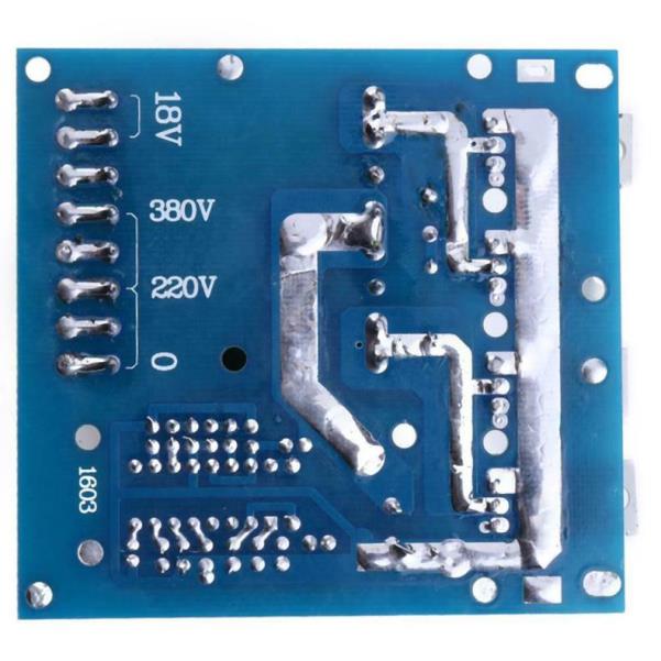
The B+ module I have found to be convenient is often advertised as "150W Inverter Boost Board Transformer DC-AC Converter 12V to 110V 200V 220V 280V" and appears to be similar to the inverter in the second photo in post #77, but includes diodes. The module pcb is nicely laid out, and has a variety of HV secondary windings to configure a few B+ levels - but I'd highly recommend the rectifying and initial filtering is done on the pcb, to minimise the switchmode loops, and if possible use smt switchmode diodes. Although the B+ output is not directly regulated by feedback circuitry, it is a stiff supply that has very little droop and whose value is directly related to the regulated 12VDC input feed. For a 6CM5/EL36 PP UL fixed bias amp, I was able to configure the HV secondaries to provide +340Vdc, plus a -60V bias supply.

One advantage of keeping the design and modules as simple as possible is that it is convenient for DIY projects, and the grounding and layout and other factors that end up determining performance can be tweaked and understood in a simpler way. Even so, a different grounding awareness is needed, as even a simple configuration has ground loops and parasitic signals to work through.
 
@trobbins ; Thank you for your post.

The module you mention is very similar to the module I am using for my 6BQ5 PP amp (see picture in post #101 of this thread). I had noticed that there were different versions of this module with screw terminals, but what had not registered in my brain was that there were versions that included the diodes/voltage select jumper.

The version you mentioned, would just need the filter caps to make a decent tube power supply for a small amp (even PP).

For my 6BQ5 amp, note that I did use some very nice fast switching diodes, and that they are located as close as practical. I also implemented basic feedback regulation and voltage adjustment.

I haven't found a version of the 500W module that includes the diodes (or even one with screw terminals).

For my next build, I plan to use the 500W module, and do the same thing -- use the fast diodes, and incorporate feedback, and I'll post any successes.

I should also note that there is a 1000W version (no diodes). The comical part is that the photo for the 1000W inverter module in numerous eBay ads shows a blown apart transistor.
 
Very interesting topic.
I have tried a couple of these myself over the years and I basically have two issues with them.
Safety and noise. Especially long therm.

Most are just really bare(ly) minimum if it comes to both.
I have blown one or two, they spit out a lot of extra garbage back into the mains (noise)
Something that definitely wouldn't pass any UL/CE regulations.
Which is to unfortunate, because it could really work out in some cases.

Since I do have experience with high power switching electronics an PCB design, I have decided to develop some things myself.
My approach is a little different, starting from a standard 15Vdc (maybe 19Vdc) power supply, which is being boosted to HV and/or being bucked (lowered) for the filaments/heaters. (6.3V 12.6V and custom)
There are multiple reasons for this approach.

The main reason is to get around any safety and noise issues directly in- and around the mains.
That way you never have live mains running into your design, which is really nice to have in general.

The second reason is to keep it modular. Someone can pick whatever power supply they want.
Following by third, easy to repair IF something goes wrong.
Even for experienced people SMPS units are a pain to repair.
Penalty is a little bit of efficiency, although still miles more efficient than it used to be, lol !

Plan is to start with something small.
Probably good for 50-60mA max @ 250-300V. good enough for a small 3-5W amp or something like a phono preamp and such.
From there on, I will make a bigger version later.

I will keep you guys updated when interested :D
Let me know what you think! Feedback is always welcome!
 

Attachments

  • HV_boost.jpg
    HV_boost.jpg
    123.7 KB · Views: 24
p-mouse, as I understand it, this thread is not about any mains converter module - the intent is to use a commercial, off-the-shelf compliant converter product, that could be replaced by any other commercial product in years to come. So your concern about safety and noise back on to the mains is not applicable to this thread afaik.

linuxslate, sorry to repeat this, but I would highly recommend looking for an 'on pcb' rectifier and filter cap solution, with caps that are just sufficient for high frequency ripple rating. Typically I have found the pcb modules have very good pcb layout for the primary side and control circuitry. Retrofitting diodes and caps requires care and attention to achieve the smallest practical switchmode current loops, that can mean cutting of pcb traces and intricate soldering (with either leaded or smt diodes like UF4007 or US1M) - I suggest that layout may not be a 'pretty' outcome, and not something that is normally seen in diy audio, but the primary aim is to minimise parasitic lead lengths and loop areas as seen by the secondary winding pcb tabs.

Another comment is that smps module use can be very dependant on FET heat removal. The OEM heatsinks may be sufficient up to a certain output power rating, but that needs to be tested, and an estimate of FET Tj made to confirm there is sufficient margin for the ambient temperature the module could sit in. Modifying that heatsink arrangement (if there is an actual need) requires care and attention, as the heatsinks are live and will be a pathway for switchmode noise egress - there are some specialist techniques for constraining noise to just pcb, but they may be difficult to integrate. I haven't looked at the higher power rated modules, but would suggest that if a simpler approach such as using individual B+ modules for each amp channel is practical, then that would have hi-fi benefits.
 
I actually forgot to tell, but in my case the MOSFET doesn't have switching voltages across it
(search for tapped inductor boost converter).

I have seen multiple mains SMPS in this topic, but my comment was just a general comment (not specifically to this topic)
 
Something that definitely wouldn't pass any UL/CE regulations.

Show me a homemade tube amp that has UL/CE approval.

My Sub-mini tube amp uses an external and unmodified 12V brick). I don't see "UL" on the bottom, but it does have CE, and lots of other little icons. In other words, the closest you can come to showing me a homemade tube amp that passes UL/CE regulations is probably the one I made with all SMPS's.

If I take an Xbox power supply out of it's plastic "brick" casing, and build it into an amp chassis, I can't legally claim that it is UL/CE listed any more, but it's actual circuitry (and thus its propensity for causing problems on the AC line) would be unaltered from the approved configuration. Arguably still closer to UL/CE than a home made amp with a "heritage" linear power supply.

I really think that assuming that something is going to feed back from a low voltage input SMPS boost converter, through both the output and input filtering and isolation of a Mains ==> 12VDC SMPS, and into the AC line is frankly not intuitively valid to me, and as of right now, no one has shown data either way.

Now, to be fair, some of what is mentioned here is directly mains powered (Such as the 2nd picture in post #103). In that case, it does seem to have at least some line input filtering, and, yes, I would recommend an additional, filtered EIC connector or separate mains filter for any mains powered audio project. The unit shown in the 2nd picture in post #103 does not have a fuse, so proper input fusing would absolutely be necessary, just as it is when using a linear power supply/classic power transformer.

the MOSFET doesn't have switching voltages across it

Cool. If it has no voltage across it, then don't bother installing it. It may have less voltage and/or lower transients across it in a tapped inductor arrangement, but I didn't see anything indicating that the switching device in a tapped inductor converter had no voltage across it.

I'm not saying I don't like it. It may be very good for low current buck/boost arrangements, but for B+ for anything that is going to power a full power amp, I'm mostly talking about units with actual isolated step up transformers.
 
Show me a homemade tube amp that has UL/CE approval.

My Sub-mini tube amp uses an external and unmodified 12V brick). I don't see "UL" on the bottom, but it does have CE, and lots of other little icons. In other words, the closest you can come to showing me a homemade tube amp that passes UL/CE regulations is probably the one I made with all SMPS's.

If I take an Xbox power supply out of it's plastic "brick" casing, and build it into an amp chassis, I can't legally claim that it is UL/CE listed any more, but it's actual circuitry (and thus its propensity for causing problems on the AC line) would be unaltered from the approved configuration. Arguably still closer to UL/CE than a home made amp with a "heritage" linear power supply.

I really think that assuming that something is going to feed back from a low voltage input SMPS boost converter, through both the output and input filtering and isolation of a Mains ==> 12VDC SMPS, and into the AC line is frankly not intuitively valid to me, and as of right now, no one has shown data either way.

Now, to be fair, some of what is mentioned here is directly mains powered (Such as the 2nd picture in post #103). In that case, it does seem to have at least some line input filtering, and, yes, I would recommend an additional, filtered EIC connector or separate mains filter for any mains powered audio project. The unit shown in the 2nd picture in post #103 does not have a fuse, so proper input fusing would absolutely be necessary, just as it is when using a linear power supply/classic power transformer.


Cool. If it has no voltage across it, then don't bother installing it. It may have less voltage and/or lower transients across it in a tapped inductor arrangement, but I didn't see anything indicating that the switching device in a tapped inductor converter had no voltage across it.

I'm not saying I don't like it. It may be very good for low current buck/boost arrangements, but for B+ for anything that is going to power a full power amp, I'm mostly talking about units with actual isolated step up transformers.
Typo on my side obviously. :(
Doesn't have high voltage. With a tapped inductor you split the voltage (depending on the ratio)


And I think you're misreading my intentions on UL/CE.
Quite a lot of Chinese SMPS are a lot worse if it comes down to safety and noise.
But anyway, I was not going to defend this little device.
Just thought it was nice thing to share.

Higher power version is also going to be very different, with a lot more safety features as well.
 
A couple more comments about what I am doing in response to @p_mouse :

Diodes:
Yes, I get that keeping the diode leads short is important at these frequencies. They are very close to the transformer, and all of the different types I have on hand are specifically for SMPS's. The filter caps are also from SMSP's, and I use "chiclet" caps in parallel (again with very short leads) to help with the high frequency stuff.

Heat Removal:
I've been a little obsessed with heat sinks ever since I learned electronics. Note the aluminum frame I made for the PS shown in post #101. That, in turn is mounted to an aluminum chassis. I also added area to the heat sinks of the Mains -> 12VDC supply. I'm pretty good at dealing with the heat. I need to get better at picking units that are more up to the ratings. Note thermal conductors/electrical insulators on the FETs to keep the HS at ground potential (and allow use of a single heatsink for both FET's.)

Speaking of this, I keep finding more. I have to basically look at everything, because you never know what words the Chinese vendors are going to use to describe their products:

There is a unit that appears similar to the 500W inverter board pictured previously, but a better design with better FETs, an included heatsink, over current protection, and perhaps
voltage adjustment. Still no diodes (just the transformer secondary as output) It seems to have the same output taps (220V, and 380V). It is rated at 600W. Search on Aliexpress for SUNYIMA 600W. Price: about $30, plus shipping.

Another group of interesting boards/modules can be found by searching "inverter 12V 1200W module" (or "inverter 12V 1200W board") These employ 6 drive FETS, and 4 just for over current/reverse polarity protection, They also include large heatsinks. These seem to have separate sets of diodes and filter caps on each output winding of the transformer. The vendor page says: Output voltage: "750V, 950V, DC 2", but I am assuming that means when taken across all 3 filter caps. Each filter cap is rated at 450V, so perhaps there is ~250V - ~320V across each one. It should be possible to adjust the voltage further by changing the arrangement of diodes/taps.

There are similar modules rated for 12V/2400W, 24V/3500W, 36V/4000W, etc. The price starts at about $70 for the 12V/1200W version.

The bigger ones specifically mention selecting the output voltage by selecting output taps as follows:
Double voltage:600V 750V 900V 1050V 1200V
Full bridge voltage:300V 375V 450V 525V 600V
They also have (6) 450V/560uF capacitors. I've found the right product, I just am not building the right project. With that kind of energy storage, I should be building a rail-gun. Other than rail-gun, I have no idea what the intended use of these boards/modules is.

None of the ads give any indication of intended use. Some of the ads mention "preamp module" but none of them look like amps at all (certainly not pre-amps). I want to see the preamp that needs a 4000W power supply. If any one knows anything about theses products, or their intended use, please post.

Update: There is a similar unit with (4) output caps and (8) Drive FETs, rated 12V/1500W and Output voltage: 560V 680V 800V
Another update: For those building either slightly more impressive rail guns, or much more impressive tube amps, there's a 24V(in)/7200W/1600V(out) version.
To make a long story short, most Chinese boards have potential (in general actually, not just SMPS), but unfortunately the board design as well as technical design is just not good enough.

As an example, there are heaps of these little Class-D texas instruments TPA boards.
Those chips by themselves aren't bad at all, I have used them in (and developed them for) OEM products.
Unfortunately, because of bad board design and technical design, they get a very bad reputation very quickly.
That's even worse for all the copy-cats (and fake IC's) that are around.

Like I said before, I think we are probably miscommunication a bit.
For instance, I use the terms UL/CE loosely.
For me it means, that a certain device is at least proper quality.
So technically speaking, no old transformers and such are officially not UL/CE compatible, true
But they are made in such a way that if there is a problem, not an awful lot can go wrong (unless you abuse it).
Also, the amount of people using old transformers is just a very small, and (therefor) most are aware it is old equipment
Which should be handled with care in general.

From a this perspective and a user point of view, a SMPS is a totally different animal.
People expect the same ease of use or at least a familiar experience as transformers (plug and play basically)
Yet, a SMPS has an awful lot more complexity and also a lot more components that can do a lot more harm in the wrong kind of situation.
In all these years, I have basically never blown up a capacitor on a regular linear power supply (except in the cases they were really old or I was just being stupid).
In a SMPS this can happen much more easily and when it happens, it ain't pretty.
In fact, I have seen power supplies literally going up in smoke and flames.

The noise part is a different story.
But my experience with most Chinese SMPS boards isn't that great.
Either the primary noise levels (back into the mains) or secondary noise levels (on the voltage rails) are just all over the place.
Keep in mind that maybe in your particular case it would work fine, but I have had serious issue with FM station not working anymore, other devices close by acting up on weird ways etc.
In the end it's just really a big can of worms. Long story short, these boards weren't developed with audio in mind.

So when I develop a product, I keep that user expectation in mind.
How easy is it to use and if something can go wrong, what's the worst thing that can happen.
Plus in many countries (not were I am from, but I am aware), working on mains is really a thing on its own.

In the end, why would I go through the trouble making a full mains powered SMPS (also means getting custom made transformers btw), with all these issues?
When there are companies that sell good and reliable products (Meanwell for example) and I just have to step-up / down the voltage with just a small penalty in efficiency?
Bonus is that people don't have to fuss around with live mains going into their builds.
Which for me is a win by itself, because (and absolutely NOFI) most DIY projects I come across aren't really what I would call safe.
Keep in mind that working on (and having potential issues with) "high voltage" mains is VERY different than secondary side isolated higher voltages.
Especially because not everywhere in the world live mains is of the same quality of safety.

 
One better method of constraining FET drain parasitic noise current loop is to use an insulator with an internal foil - the foil is returned to a switching stage rail, and acts as a screen to noise currents flowing over to the actual heatsink (which in post #101 would be the aluminium sub-chassis) - there used to be commercial insulator products of that design, although the same can be done using a DIY construction, and keeping the link from the screen and the pcb node as short and direct as possible.

The image below is the 12V 500W inverter pcb - it looks like some of the secondary side former pins are not used, which would certainly make it easier to use as spare terminals for making up whatever rectifier and filter configuration suited the application.
12V%20500W%20pcb.jpg
 
- it looks like some of the secondary side former pins are not used, which would certainly make it easier to use as spare terminals for making up whatever rectifier and filter configuration suited the application.

Yes, the other pins/holes are not used (No actual transformer tap connected to every other pin.) So Yeah, mounting diodes there is a good idea.

In addition, I'd like to point out that since the 18V connections are a separate winding, they can be used to generate a (-) voltage for bias just as one would use a separate winding of a 60Hz transformer, just make sure to use fast diodes, and high frequency filtering because this is one place you'll really hear any noise, esp. on a SE amp.
 
Bumping this thread because I have some updates...

First, an update on what I have been working on:

tube_ps_1.jpg

This picture shows (from bottom up) a 12VDC 20A SMPS driving a 380VDC power supply based on the previously mentioned "500W" inverter board. I am using (3) 60W light bulbs in series as a load bank.

I'm still working on this. As of right now, it is no where near being acceptable for actually powering an amplifier. It's unstable in both output and thermally. It will produce almost 380V @ 700ma, but is sings (audibly -- a high pitched whine), and it is completely unstable at certain voltage settings. Note however, that 700ma is almost twice what I need for the planned amplifier, so I may still be able to get this running "well enough". I don't know yet.

As you can see, I have added a bridge rectifier made from 4 high speed switching diodes, A filter cap, and a simple feedback circuit.

The 12VDC power supply is probably running at about 10-12A, (rated @20A) so it barely gets warm at all, which is impressive for such a compact power supply.

I'm not sure why (3) 60W bulbs add up to over 260W, but I need to get some smaller bulbs, or another suitable load.

Note that they are "bug lights", because that is the only kind of incandescent bulbs I can find these days.

More news as I continue learning, but I wanted to post today because I have finally found what I have been looking for:

tube_ps.jpg
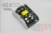
These seem to be something new (from China, of course), as I am sure my searches would have turned these up before if they were out there.

They are rated for 250W total: 300V@600ma, 12.6V@4A, and 6.3V@4A. They advertise a 30sec delay on the HV start up to prevent cathode poisoning.

Note that it says 110/220VAC input, so I assume that means it is actually wide input range, and should give a regulated 300V output with any input from 100VAC to 240VAC.

The HV output does not seem to be adjustable, and I don't see any options other than 300V, but some of the vendors do mention "customization". 300V is anemic for my P-P 7591A project, but it's plenty -- even with de-rating for a P-P 6BQ5/7189/6п14п project.

Now that the US holiday rush is over, I intend to order some of these, and some of the previously mentioned 150W units.

In addition to the 7591A project, I have tubes, chassis and OPT's on hand for a build based on (probably) the 150W SMPS.

I'm not posting any links, because this thread is not about advertising any particular Chinese vendors or sites.
 
I have received 2 of the 300V/250W PS's mentioned in the previous post.

I wouldn't say I've thoroughly tested them, but here is an initial review:

As shown in the previous post, the listing mentioned 110/220 VAC input, but as I suspected they are "wide" input range, not just a manual or automatic switch.
IMG_20210118_2_s.jpg

Note the adjustment to the right of the terminal strip. This pot adjusts all 3 outputs.
IMG_20210118_1_s.jpg

(Note: The watermarks are not intended to advertise my site. They are intended to prevent the picture from being used in ads/listings.)

Mine showed 300.1 when I first powered it up, but that made the heater voltages a little on the high side -- like 6.6, and nearly 13VDC (no load). With the 6.3 set to -- 6.3, the 12V was just over 12.6, and the 300V was just under 280V. All this is fine for the intended project. With these adjustable SMPS's, I set the heaters just a couple tenths low for good heater life while still having good cathode conditions. In this case, that means I guess I'll take what I get for B+.

Interestingly, there seem to be 3 opto-isolators on the board implying 1) true isolation, and 2) individual feed back. So I am not really sure why there is one pot for all 3 voltages.

So how about noise? Well, Arm your "I told you so's"... You may (or may not) need them...

Fluke_SS_Chinese_Tube_SMPS.jpg

The first capture is with no load (We are looking at the 300V output set for 280VDC). The second is with a small load (only about 20% of rated). I haven't taken more captures, and I'm having problems finding a really appropriate load, but they don't seem to get much worse as the load increases further.

Before you unload on me about 30V P-P ripple on a 280V PS, keep in mind that it's not like 30V P-P of 60Hz PS ripple from a linear power supply. The actual ripple looks pretty good if you overlook the spikes. There isn't much energy in those spikes, so it should be pretty easy to further filter. It's actually a much better story than the P-P value would suggest.

On that note, I don't see any inductors on any of the outputs. I think at SMPS frequencies, inductors are really important for someone (me or the Chinese) trying to push these things for audio use. I must assume that they intend that the inductors and further filtering are a downstream part of the amplifier.

I would also like to note that there is filtering on the input, and my amp will use an IEC connector with an additional filter in it. I'm not really concerned that these things will put stuff back on the AC lines any more than any other modern device (like a TV or PC) would.

There is also no audible whine at all coming from the unit, even with the biggest load I've tried so far.

Fields:

I see that same spike pattern even when my test leads are just laying on the bench. One solution may be to mount them upside-down inside the chassis, or right side up above the chassis. In other words to keep some grounded metal between the SMPS and amp circuitry -- especially the input. I'm not sure what mounting them upside down does to them thermally.

Thermal:

So far, I have not even gotten it warm. It's partially that I don't have a supply of mult- hundred watt resistors of different values, but also that I am having a problem measuring the current. Those spikes or the high voltage (or something else) is messing up 2 different directly connected DMM's set to mA/A. I have a 1.5K, 25W resistor clamped to a large heat sink. That should be 200ma@300VDC, but 2 different DMM's measure over 800mA. I don't have an analog VOM, and my clamp-on meter is at another location.

I have the bank of series-wired light bulbs that I made, but I am hesitant to do a long-duration test without knowing the actual load. First, I want to test the PS, not kill it, and also any data would be kinda meaningless without actually knowing the load.

Also note that I am only loading the 300V output. It would take as much effort to build a full dummy load as it would to just build an amp.

Delayed start:

There is a 15s delay from the PS first turning on (Heater voltages being on) and the 300V turning on.

Where it stands now:

As mentioned, the best load for a tube amp SMPS is -- [fanfare] -- a tube amp. So I intend to keep going. I am building an simple 6п14п P-P stereo amp for this PS. It will have a toroidal choke, and a R - C divider chain downstream of this PS. I think it will actually work fine. My biggest concern is a tight chassis, and stray fields. The build thread for the 6п14п P-P amp is here.

Also, before this amp arrived, I continued working on the larger 380V supply previously pictured. I was concerned about the amount of ripple/spikes on that power supply, but it is actually much better than this one. I'll post an update on that other one at a latter time.
 
Not bad at all. Without the spikes, the noise is quite low.
Are the spikes 20us apart, so 20Mhz frequency?
If it is, so that could be easily filtered downstream to have a quieter PS.
 
Post #120 scope shows 50us period (20kHz) spikes, with spikes at 40kHz under load. Those spikes should attenuate well by carefully integrating a leaded inductor (eg. https://www.tdk-electronics.tdk.com/inf/30/db/ind_2008/b82144a.pdf) along with a small cap - preferably on the pcb. Close inspection of the pcb and parts may well show up other options for transient attenuation on the pcb - not just for the B+ feed but also the heater supplies, as heater spikes can easily couple in to audio signals, and it would be recommended to constrain transient filtering to just the psu/pcb and not out-board filters.

The pcb should also be inspected for how it connects the incoming protective earth, and if the 3 secondary supplies have common elements, as switchmode transients can loop out and around heaters and B+ circuitry, and it may be advisable to have the amp's single 0V to chassis link integrated with that psu/pcb.

Was there a metal top cover for that psu, or was it plastic or just an open-framed psu ?

Wrt testing and loads - I would recommend not using incandescent bulbs, as their resistance changes a lot (the reason they are used for light bulb limiters for servicing).

During testing, it would be useful to test the heater supplies in to your target valves, as the turn-on heater current may well exceed the supply current limit rating, and you need to clarify if that is safely and adequately managed (eg. by hiccupping or current limiting as the heaters warm up).

Wrt the earlier psu and it being unstable - I'd anticipate that is due to the use of feedback - and make the comment that adding feedback to regulate the output of a power supply that didn't have feedback is likely unnecessary, as the regulation is likely to be quite stiff (and exceed the stiffness of any normal valve amp power supply).
 
@trobbins and I were typing at the same time. He beat me to the [Post] button.

So the scope meter is set to 20µs/div, and there is a spike about every 2.5 divisions right? (looking at 1st picture). So that is ~20KHz according to both my (admittedly poor) math, and an on-line period-to-frequency calculator.

I don't think my scopemeter can see 20Mhz (or just barely).

When I added a load, I either got higher frequencies (a little under 50KHz?), or maybe the scopemeter was just having difficulty triggering.

20KHz should be pretty easy to cut down significantly with a choke (series) followed by another electrolytic (to ground), and bypassed with a chicklet cap. (Something I was taught -- "Big capacitors make really bad small capacitors.")

There's a small disc capacitor near the output, but I think it's filtering the feedback. Or it may be protecting a Zener that is clamping the feedback. I don't think it is bypassing the big electrolytics.

I can't really reverse engineer this thing without taking it out of the aluminum chassis/shield/heatsink, and with all those parts thermally connected to the aluminum, I'd rather not do that.
 
Back
Top Bottom