• The move to the new server is done. There are some software and database maintenance updates in process. This has us passing the hat around to help out. We appreciate any donations. Seriously, even a dollar helps. The payment page may be found here - https://www.audiokarma.org/support.html

Modern Power for Tube Projects?

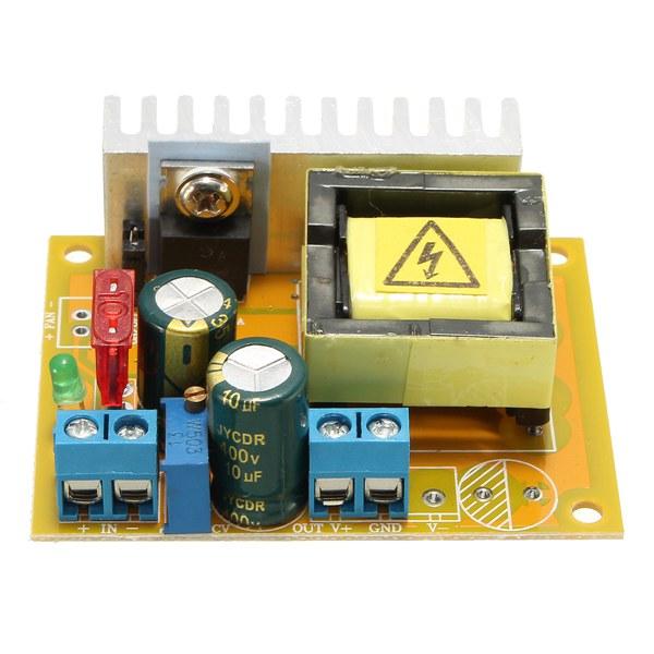
Item 112712645973.
(No affiliation with vendor.)

You can find several vendors for this particular module by including "420V" in your search. E.g. "power supply 420V".
 
OK, so all these modules run on 12V DC Input. Where does this come from?

--- Bet you can't guess -- A Chinese Module!

IMG_20191031_ps_sm.jpg

This is a 100-240V AC input to 12V DC @ 8.5A Switch Mode Power Supply.

It is also a great illustration of what @Retrovert was talking about. For a PS rated at 8.5A, it weighs practically nothing.

Not only does it have very few, and very wimpy parts, but half of the parts marked on the PCB are not even installed. This includes a space for what I think should be some sort of thermal diode or thermal cut-off. At least is is fused.

I had to open it because it arrived slightly dented and bent -- and that is from a US vendor. There was no packing except it's basic cardboard box, and a shipping bag. Notice that the "integrity" sticker is still intact. I was easily able to lift that sticker, remove the top, and stick the sticker back down. Apparently, the Chinese don't quite get the concept.

One good thing is that the ground from input to output is isolated. The terminal with the ground symbol (incoming mains ground) is connected to the chassis, but isolated from the -V terminals. I'll connect the IEC center terminal to ground, and a nearby screw on the case. The -V will be common with all of the various PS modules, and (thus) signal ground.

This should make the unit both safe and less subject to ground loops.

I haven't powered it up yet. I could use the same halogen auto headlight that I've been using as a moderate load, but my retinas and the fire department would rather I don't. I think I'll take what I get.

If I find a suitable and non-blinding or fire prone load, I'll post results.
 
auto headlamp with a "hat" made of aluminum foil should do it. Or drop it in a bucket of water if you're feeling adventurous.
 
I'm following your proceedings with interest !

I will be starting a thread for the actual build as early as this weekend.

We'll start with a teaser of a table full of parts. Next will be a chassis layout drawing. When I think I can take the abuse, I'll post a schematic.

Even if I start a thread tomorrow, I may not be able to actually start building for a while.

I don't have the chassis yet, and my drill press is in storage, so it's kind of hard to start building without a (drilled) chassis.

:lurk:
 
I'm buying modules, and I can't stop!

While ordering other electronics from certain vendor on "A popular auction site", I noticed the same vendor also sold some heftier "buck" modules -- so I added a couple to the order.

These are rated at 150W/12A, so it is sufficient for all of the filaments of even a fairly elaborate build. I am also hoping for less ripple and more longevity by having much more overhead in terms of rated amperage.

The listing says:
Output current: 0-12A long time natural heat within 8A, the temperature does not exceed 60 degrees. Please reduce power when the ambient temperature is high.

And in my installation, it will be inside the chassis with other hot items, and only a little convective airflow. I calculate ~4A total for all filaments (at 6.1V), so the 5A module I was planning on using may be cutting it too close.

This also has a current limit setting (Pot on left -- note wire shunt.)

I'll post an update after testing.

EDIT: Forgot to attach picture...12ABuck.jpg
 
I'm buying modules, and I can't stop!

While ordering other electronics from certain vendor on "A popular auction site", I noticed the same vendor also sold some heftier "buck" modules -- so I added a couple to the order.

These are rated at 150W/12A, so it is sufficient for all of the filaments of even a fairly elaborate build. I am also hoping for less ripple and more longevity by having much more overhead in terms of rated amperage.

The listing says:
Output current: 0-12A long time natural heat within 8A, the temperature does not exceed 60 degrees. Please reduce power when the ambient temperature is high.

And in my installation, it will be inside the chassis with other hot items, and only a little convective airflow. I calculate ~4A total for all filaments (at 6.1V), so the 5A module I was planning on using may be cutting it too close.

This also has a current limit setting (Pot on left -- note wire shunt.)

I'll post an update after testing.

EDIT: Forgot to attach picture...View attachment 1679706

Yes, there exists a lot of modules, both mains => DC and DC => DC (B+ and filament)
Provided one can get them silenced they seem to be all you need to a preamp or RIAA stage.
 
I initially wasn't going to say anything, as the quality is pretty much as I called it and it's your call if you burn down your house. But someone else may follow this path, and burn down theirs, so I'm briefly and quickly commenting.

Any safety or emissions certification present for this unit will be fraudulent. Take the EMI suppression to meet FCC requirements, for example. Amazing engineering! It's been so well engineered it is so compact it takes up no space on the board! No X-cap, no Y-cap, no choke. (Well, that might be an X-cap near the terminals.) Talk about Chinese miniaturization! I'm equally impressed by the heatsink designs, which is described as "Please reduce power when the ambient temperature is high." Now that's an amazing way to design a heatsink! Then the inductor's proximity to the electrolytic will bake it and cause early failure. No fuse, PTC, or thermal-cutout.

This power supply clearly cannot meet the FCC requirements or the UL/CE requirements; if it contains such certification that would be fraudulent. Certainly would not be the first time the Chinese did this.

The proximity of the inductor to the output capacitor is a poor choice, as the capacitor will eventually fail from premature aging caused by overheating (below see). I expect those capacitors are not rated for high ripple current, either which will shorten the lifespan.

But I see a more serious problem which I will call to your attention because it is dangerous and may lead to fire.

As per the thermal warning, the powdered-iron core forming the toroidal inductor may be prone to overheating, which is a fire hazard. The short version is that core losses in powder-metal cores depend upon core temperature. So as the core temperature rises, the losses rise. The maximum saturation flux density decreases with temperature, so as the core temperature rises the core more readily saturates, increasing the temperature. Thermal runaway begins. At some point the core surpasses its Curie temperature, all magnetic properties cease, the Rubicon is crossed, and the core catastrophically fails. The core's properties may also become damaged with repeated overheating, leading to premature failure.

Because no fuse, PTC, or thermal-cutout is present the overheating is not interrupted, and a fire results. Well, maybe the mains fuse for the unit kicks in before that point.

I again suggest comparing the board complexity to more expensive units and considering what was omitted, and comparing the board layout to more expensive units and considering why the differences exist.

I'm sure more problems exist. Don't burn your house down with this. Add some fuses and thermal cutouts, and move that inductor away from the filter capacitor.

Barbie says, SMPS Design is Hard!
 
You realize that this is a buck converter, and not a full power supply right?

The device shown in post #70 does not connect to AC "mains" voltage.

Input will be 12VDC from a separate SMPS (shown in post #66).

The AC power supply (shown in post #66) does have an internal fuse (and the EIC socket that was provided with the chassis I will be using also has a fuse).

The module shown in post #70 only servers to reduce the +12VDC to an adjustable and regulated filament voltage (which I will set to 6.1V, for filament longevity).

Max input to the buck is 32VDC, and must be at least 0.8V above the desired output (a little more if the input voltage is very low -- i.e. it needs about 4V in to produce 1.5V out). Since this is a buck, and not linear, it's not restively decreasing the voltage. Thus there is no other maximum input-to-output voltage, and how hot it runs mostly depends on the total wattage -- very little on the voltage drop from input to output.

Yes, I could run the 12AX7 filaments in series, and run them directly from the 12VDC source supply, thus reducing the load on the filament buck, but since I must have 6.1 for the output tubes, and these things are 90-something percent efficient, I see it just as practical to run all of the filaments off the buck that is set to 6.1.

I don't see how this module, running downstream of a power supply that is fused (and at least presumably has other protections), and with another fuse upstream of that, is going to set my house on fire.

I've never seen safety ratings or EMI ratings for downstream power supplies or voltage conversions.

A place I used to work ran into this issue. The device that we built in house was not UL listed, and thus could invalidate a customers insurance. We simply moved the PS to an external brick -- which was UL listed -- and ran it to a 12V connector on the back of our device. We were then good to go, and our customers could use it in their building with no insurance problems.

I also don't think that most hobby-built, mains powered devices (especially tube amps) are or could be rated as you mention. I don't think that is a reasonable criteria for any home built amp mentioned on these forums.

I would also like to point out that the B+ (high voltage) boost supply is also fused internally. (The screen supply buck is not) I suppose adding a fuse between the 12VDC, and the filament buck would not be a bad idea, but I also do not think it is necessary.

I'm quite sure that my use of a mains SMPS, and downstream SM boost/bucks makes my design both safer from both a fire/external shock point of view, and from a testing/troubleshooting point of view, as compared with a classic tube power supply. It is also much more efficient than a classic tube amp power supply despite the down-and-back-up series of voltage conversions.

While I plan on having at least 5 total modules in my amp, it also takes up less total "volume envelope" than a classic 60HZ power transformer, tube rectifier, can capacitor, resistor chain, layout.

From an EMI point of view, I find it hard to believe that it will cause problems for anything other than itself.
 
EMI is emitted anytime switching occurs, and snubbers are for this reason routinely used. The physical design of that supply has at least the issues I raised, including the proximity of the capacitor to the hot inductor. The caveat about reducing power output with temperature suggests inadequate cooling and a potential source of failure. Again, the powder core may fail with temperature rise at which point the unit turns into a dead short and passes whatever current it may pass. I have repaired units where tantalum filter capacitors failed as shorts and became hot enough to scorch the board, and yet the supply fuse did not blow.

We return you to your Made in China marshmallow roast.
 
Just wanted to update this thread with some more information as I build and learn at the same time (I think that is called "experimenting").

Over in my EL84 amp build thread I've been running into some difficulties (No... No fire yet.)

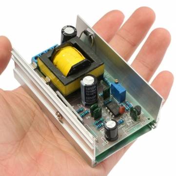
I ended up using the small unit mentioned in the first post on this thread (shown below) for my Screen/driver/phase inverter supply. That seems to be working well, and it barely gets warm.

fd36d100-979b-400a-a29c-460433085bae.JPG


The intended plate supply, (shown here:)
7a1500f5-b04d-4b80-89f4-2cc6157a0811.jpg


Was found to be not up to the job of running 4 EL84's.

I do want to note that the low voltage (100-240V) version of this power supply has been in use in my subminiature tube amp project for well over a year now. That amp is used daily (PC speaker amp). It's running 4 subminiature tubes (P-P). It is power cycled a lot, and has been inadvertently left on for extended periods of time on several occasions. That amp is also dead quite in idle.

I feel that the above power supplies are fine (and safe, assuming a safe source of the 12V input) for a flea-power amp, or single channel, single ended EL84 amp, but a Push-Pull, Stereo, EL84 amp, running at 320V plate voltage, and >40ma/tube cathode current is by no means flea power. The above power supply just won't cut it.

Running even under the rated 40W continuous, at ~300-320V, the above unit will overheat, and become very noisy after a short period of time. The 40W continuous rating is probably accurate for lower voltage settings, but as you increase the voltage and/or the load, the efficiency decreases exponentially.

Note that I had a basic math error in my initial calculations for the supply requirements for my PP amp design. If it were not for that error, I would have realized that a single one of these would not satisfy the power needs of that design.

For a single channel (2 EL84's), the above power supply will operate indefinitely, and that is in a room with an ambient temperature of about 80F, and attached to the same chassis as the tubes (>100F from sources external to the PS).

So the obvious solution is to simply use one for each channel, however, I still feel that this is marginal from a thermal point of view, and possibly not 100% quiet in idle.

So... I have returned to basic research. Along the way, I have found a couple of interesting things that I would like to share in this thread for completeness, but I'll break it up because nobody likes long posts.
 
The "top one" in the previous post _should_ be able to support 2 EL84 ( and some preamp duty).
Thus 2 of these would fulfill your needs . Or ?
As for filament, i still think you could series connect EL84 and use the 12VDC as source for all your tubes.
 
So with further research, I have come across some other interesting ideas for powering a tube amp with SMPS's.

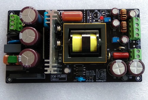
This looks like the closest to what I really have in mind:

s-l500.jpg


This is from an eBay vendor (no affiliation, no knowledge of, or dealings with this seller.)

It may look like a regular switching power supply, but it has a DC200V-520V (customize by the manufacturer, not adjustable) output.

It also has a (-) bias output (adjustable) and several outputs for heaters and DC aux outputs.

The vendor claims 300W-400W continuous and "1000W power generated during dynamic signal impact, less than 100 megaseconds" (so as long as that bass riff lasts less than 3 years, you'll be fine).

The vendor doesn't specifically state the current rating of the HV output, but he mentions "KT88" in the auction title. So one must assume they are not talking about a flea power amp or pre-amp.

Unfortunately, it is expensive ($140), and set up for 220VAC input. Perhaps both are "customizable".

I should also not that the basics (transformer, rectifier, misc parts) will cost at least as much for a conventional power amp power supply.

It certainly looks like someone else is thinking along the same lines as I am.

-----

They are also thinking the same thing over in Russia:

http://www.klausmobile.narod.ru/projects/pr_05_carpower_e.htm

(Second schematic is the SMPS plate supply)

Here is a 12V input, 250V @ 300ma output step-up switcher.

From my research, this has a number of features that are essential for an adequately efficient, noise-free plate supply SMPS:

  1. Push-Pull transformer drivers
  2. Full wave or bridge rectification on the output side.
  3. True isolation, including the Opto isolated feedback (As typical for "normal" or down SMPS's)
  4. Good filtering of the output.
Note that he even made his own transformer.

----

Another Approach:

I also keep seeing these pop up in my eBay searches:

140W_Inv.png

These are the inverter section only. In other words, the output is the high frequency AC right from the secondary of the transformer. A rectifier and capacitor(s) should produce clean DC. It wouldn't technically be regulated, but of course classic tube amplifier power supplies aren't regulated at all. Different taps and different diode arrangements should result in a wide variety of available voltages.

Edit: Input is 12VDC.

Apparently the switching frequency is around 20KHz. Ideally it would be higher to stay well clear of the audio band. Fast diodes of sufficient ratings would be needed for the rectifier.

These are available in different layouts, and with or without heat sinks included. There is also a 500W version with 4 driver transistors.

 
The "top one" in the previous post _should_ be able to support 2 EL84 ( and some preamp duty).
Thus 2 of these would fulfill your needs . Or ?
As for filament, i still think you could series connect EL84 and use the 12VDC as source for all your tubes.

I guess that in addition to the math error in my Wattage calculation, I also did not notice that both units basically claim 40W, 70W max.

So it is possible that 2 of the little ones could suffice, but they sure look awful wimpy to run 4 tubes.

I'll put them on the bench, and see how they actually compare to ones I had been using, but I think I really need something more "beefy".

Yes, I am seriously considering re-wiring it to run the power tube heaters in series pairs.
 
Sometimes switching supplies have noise, I have a LED lamp switching supply wall wart that wipes out my AM and shortwave reception all over the house

Yes, and why I want to see these supplies strictly regulated on RFI/EMI allowable. These spew garbage and hash too often and ruin radio reception. Use a proper transformer linear power supply, please.
 
switchers can be clean. The supply I used to use for DC radio gear is absolutely silent. I've sniffed it with the scope and with shortwave radios, never found a noise spike. The lights in the shop are a different story entirely. The filter banks in my 40a supply are a whole lot more extensive than I expect the $25 shop light ballast has.
 
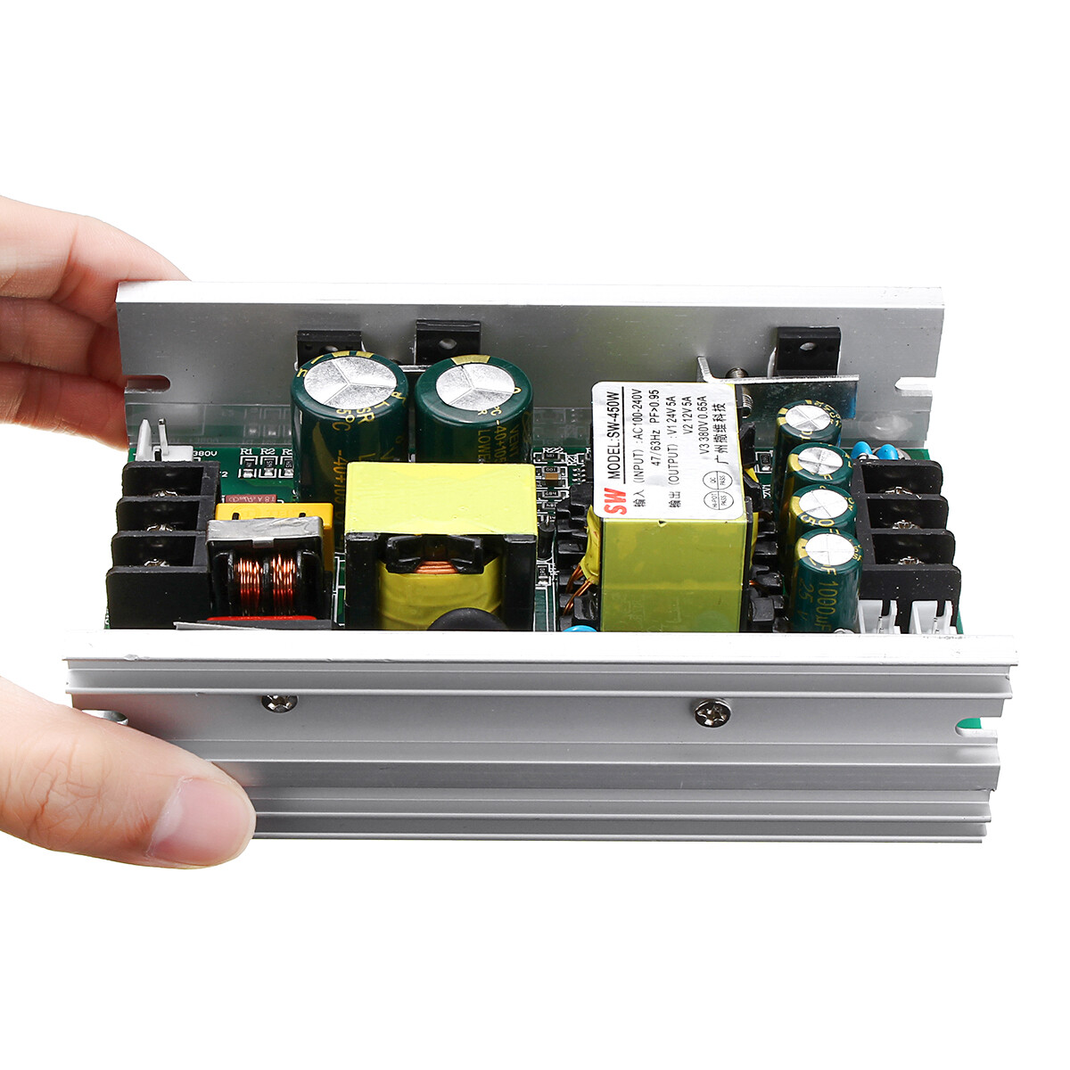
So I have also come across these:

s-l1600.jpg


(eBay image -- no affiliation -- image will "expire" at some point)

The are intended for "moving head" arc lamp light show lights.

I used to work for a company that made a very early version of something similar. It was basically a laser light show head, but with a arc lamp instead of an actual laser.

Apparently there are lots of Chinese clones of a popular light show unit, and thus lots of Chinese versions of the PS.

Note that these run from 100 - 240VAC input. They are isolated.

At first, I thought that the +380V output may only be the trigger to start the arc in the arc lamp, and thus be rated at a very low current rating. Since the vendors selling these sorts of power supplies are selling them as replacement units, they don't typically provide the power supply specs.

However, if you look at that picture carefully, it says that the 380V output is rated at 650ma! An Alibaba site that did list specs for a similar unit also listed the output rating of each output. That's an order of magnitude more than I need for a full stereo P-P amp.

My problem isn't wimpy power supplies, my problem is wimpy tubes!! I need to order some 7189's! -- Just kidding.

That one also supplies +12V @ 5A and +24V @ 5A -- Plenty for lots of heaters -- either wired in series, or powered via another small buck converter.

There are lots of other very similar designs. With slight variations on the other voltages and currents, but all of them seem to indicate that the HV output is 380V.

Note that one of the DC outputs of for a fan. It's likely that both the PS and Light head is fan cooled, however, in a tube amp, I would likely not be using the 24V output, I would as mentioned, be loading the 380V output at <1/10th its rating, and even running all of the heaters, I'd be using half the rating of the 12V supply. It should be fine without a fan.

They look pretty basic, and assuming they use a standard SMPS controller chip (and assuming the datasheet is available for that chip) figuring out how to adjust the output voltages should be fairly easy -- If not, then there's always the conventional power resistor to drop the output voltage -- or perhaps I'm not kidding about 7189's or Russian tubes.

I'm going to order one of these things, and see what happens when I warm up some power resistors.
 
OK, More setbacks/disappointment...

The power supply pictured in the previous post arrived a few days ago. Sadly, it was damaged due to poor packaging, and also seems to suffer from poor quality control.

Worse than that, due to it's basic design, I don't think I would use it.

The main problem is that the +380V supply is not isolated. (Remember that this PS runs from mains powers, not 12VDC). The 12V and 24 V outputs are isolated from the AC mains.

The +380V portion is based on an L6562 controller, a typical application can be seen here (-Not- a schematic of the received PS):
https://www.arrow.com/en/reference-...pfc-controller/c4e82e0ce725d6ece8d1dfc2310ef2

There are also quality control problems. I believe the QC problems are separate from the damage due to improper packaging. One of the DC (output) legs of the main, incoming bridge rectifier is loose from the PC board (insufficient solder). Note that this would affect the +12 and +24 V supplies as well, and due to the voltage/current at this location, there could be arching/heating with a bad solder like this.

Also, apparently this type of power supply, is apparently very noisy -- especially on what it puts back toward the AC line.

That said, it does look like they made attempts to block the noise.

-- There is an incoming EMI filter (closet to the terminal block on the left in the picture in the previous post.)
-- Details such as a ferrite bead on the leg output diode of the HV supply.

I think if the 380V supply components are removed, and some of the larger solder joints are re-done, it will probably be a fairly quiet +12V +24V supply, but that does not help me get closer to a stable/clean source of +320VDC.

The next plan is to use the mentioned "Inverter" modules, and to build my own HV rectifier / filter circuit.

Some 1KV, 2.3A fast recovery glass diodes ordered for this purpose have already arrived, and the "Inverter" modules should arrive this week.
 
Back
Top Bottom