• The move to the new server is done. There are some software and database maintenance updates in process. This has us passing the hat around to help out. We appreciate any donations. Seriously, even a dollar helps. The payment page may be found here - https://www.audiokarma.org/support.html

Modern Power for Tube Projects?

The point with this excersice is to use switch mode power supplies instead of heavy and hard-to-get transformers.
To get 12V DC is easy, and usable for many tubes. The x00V is more difficult, but for low powers it
seems within reach.

One issue : elevated filaments is needed in some circuits, the easiest way is to use separate small
12V supplies for these.

Large 500V @500mA seems out-of-reach for the moment, but future will show.
 
Power transformers for vacuum tube P/S are still easy to get.
http://www.hammondmfg.com/5cpwr.htm

If you (the OP) or anyone else in this thread decides to do a series-string, killer amplifier -- please, please, please use an isolation transformer.
You only live once.

You can make an isolation transformer with two solid state-style (e.g., 12V secondary) power transformers of suitable VA capacity connected together secondary to secondary (i.e., a net 1:1 pair of transformers physically isolated from the AC mains).

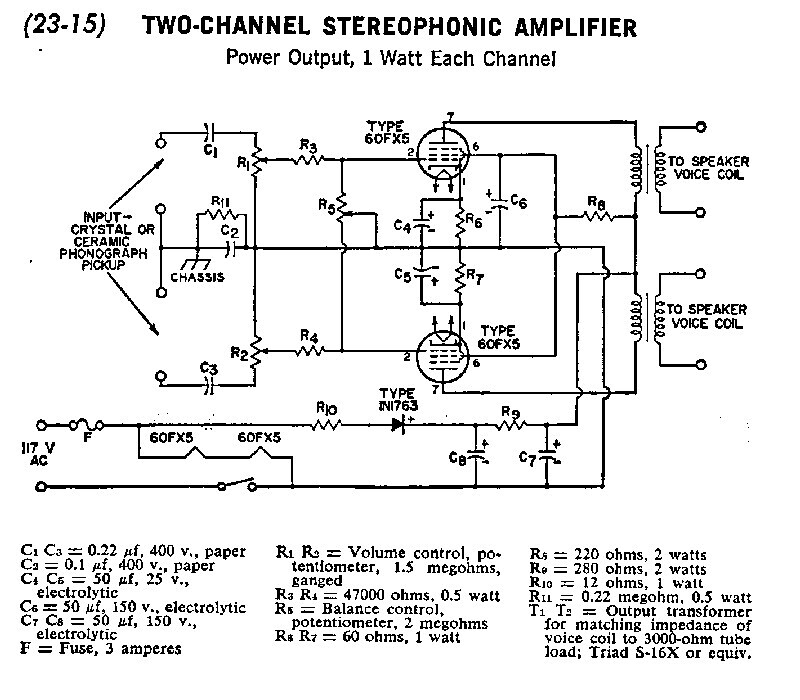
Here's the dumbest, simplest amp you can build, if you want to go the killer route. :)
Something like a CD player (with attenuation on the outputs) should drive this pretty well if you don't happen to wish to use a crystal or ceramic phono cartridge ;)

60FX5stereoampresized by Mark Hardy, on Flickr
 
I'm not going to do anything that is "transformerless" or even remotely "hot chassis".

It's true that the HV SMPS is non-isolated, but using a common wall brick provides both isolation and grounding.

I just checked, and the barrel of the 12V connector is connected thought to the ground of the 3 wire plug.

The PS only cost $12, and the regulator was $7.

I don't think you can beat it for safety or $$$.
 
I used one of those HV power supply for aging caps.

It makes a lot of noise. EMI and physical noise. Ripple was also bad.
I would stay away from switched PS in an audio amp unless properly shielded and filtered.
 
OK, bumping my own thread, but I am still a bit obsessed with these inexpensive Buck, Boost or linear power modules.

First, an update:

I built the my Subminiature tube amp project using the power supplies mentioned in post #15 of this thread. The amp has been working since early this year, and since it is my PC speaker amp, it is actually the tube amp I use the most.

The Filament power supply is a buck converter that I litterally sawed out of a piece of networking equipment. It's based on a LM2576, and works better than any of the buck modules I purchased. It's also cosmetically better with a nicely enamaled coil, and a blue anodized heat sink I added.

The next step:

So now I want to take this to the next level -- or perhaps to the extreme...

I want to build a basic 6BQ5/EL86 Stereo Push-Pull amp. It will have a basic 12AX7 Driver/Cathodyne inverter. Basically a Maggie 9300 clone, except it will be grid biased.

In doing some research, I came up with the thought -- What if I stick these little buck/boost supplies basically -- everywhere...

Plate voltage (B+): Use the 200-450V version of the above mentioned PS. That power supply is rated at 70W, and some vendors say "70-100W". 70W @ 300V is 233ma, so running a complete stereo P-P amp may be pushing close to that. Using 2 (one per channel) would not be a problem.

But what if you took this idea further?....

Want to run the screen at exacty 10 volts under the plate? (or 5V or whatever...) How about just adding another (perhaps lower current --- see the unit pictured in the first post in this thread) module. These things are as small and cheap as a few resistors and another capacitor, so why not? Why use Ohm's law when you can get whatever you want by turning a trimmer? Wanna see if screen voltage affects sound?

Hypothetically (I don't currently plan on actually doing this), but why not run the driver/inverter (12AX7) off of another (separate, even cheaper) one?

I'd need to drop in at least 2 buck converters for the Filaments, probably, one per channel. How about buck converter in front of each linear soft start module -- more efficiency, and...
More modules !!!:banana:

I've found a Chinese module with a high voltage boost converter (plate), and a linear regulator (filament) on the same board. I think it was used or intended for Chi-Fi pre-amps. It could be used for the screens and/or the 12AX7's. Any B+ provided separately is load off of the main (final) plate supply. Having them separate reduces the need for a resistor/filter chain.

Then there is grid bias: No need for a separate winding, there are Buck/Boost converters that take a single ended input (e.g. +12 only), and give you adjustable plus and minus 5V-24V. Again, I'd probably use 1 per channel, but if your preference is for a separate bias control for each tube, again... these things are about the size of a vintage capacitor, better looking, and a few bucks a peice.

Guess what the whole thing would run off of? --- An internal 12V Switch mode power supply chassis. (No body likes wall warts or bricks laying around on the floor.)

Advantages:

Lazyness: No power supply calculations.
Safety: Line isolation. To be clear, I am *not* talking about modules that rectify, filter, and regulate straight line voltage. I don't recomend those, or products that use them.
Noise: These modules operate at high frequency which is much easier to filter.
Tube Life: Immune to high line voltage (Isolated by regulators in both the 12V primary supply, and the Buck/Boost circuits.) Drive tubes as hard or easily as you want. These also seem to be fairly stable over time.
Cosmetics: Mount larger/Cooler looking ones on top of the chassis, fit smaller ones underneath -- builder's choice. With anodized heat sinks, and cool-looking inductors and LED's, I think these actually add to the looks of a project. Since they are rectangular, small, and sometimes partially enclosed, it is easy to build a safety enclosure for parts mounted outside the chassis. They definately look better than a silver can or open frame transformer. To most people, big, brightly enameled inductors look "vintage", "sci-fi" or "Frankenstiens lab" -- a look that goes well with exposed, glowing tubes. I don't think anyone will say "Hey - They didn't have LM2576's when amps used tubes!"
Keep the signal path pure tube: Nothing I am talking about introduces semiconductors into the signal path.
Cost: These modules average about $5 to $20 a piece.
Simplicity: Yes, the component count of a SMPS, or Boost converter is higher than that of a classic power supply, but if you count these modules as single components, the parts count should be the same or lower. If they fail, they can be replaced as a single component.
Efficiency: OK, so tube amps will never be "efficient", but even with a double conversion (Line --> 12V ---> B+), overall efficiency of the power system should be as good as or better than a classic power supply.


Astute readers may note that I placed Lazyness (avoiding doing maths) above safety. While the order was not intentional, it is obvious that I recognized it, and did not change it.
:p:(:eek::rolleyes::crazy:
 
Diyaudio member Kodabmx has several threads on using inexpensive switch mode power supplies for tube projects.

In the "Ganged switching power supply for tube amp" thread he starts with all the supplies he uses in a high power amp.

I have bought the parts he mentions and intend to do the same.

Steve
 
Some of the 6.3v AC to 6.3v DC converters with a regulator are nice for heaters. You can even get 20 amp versions for pretty cheap.
 
Fisher EL84 amps are probably a better basis if you want split load. Magnavox amps are paraphase.


If you're looking to peg the screen at a lower voltage relative to the plate, EFB might be your answer. Thats a regulator setup, but it references off the B+ so the relationship in those voltages is maintained. Better distortion performance doing it that way.
 
Fisher EL84 amps are probably a better basis if you want split load. Magnavox amps are paraphase.

Yeah -- guess I showed that I am not really that familiar with the Maggies. What I have drawn right now is a copy of a Packard Bell (Schematic attached in 11th post in this thread), but with fixed bias. (Voltages, and other changes accordingly). The PB amps have a direct-coupled Driver/Cathodyne stage, and that is what I want. I copied that in-tact.

I ordered some of the mentioned negative voltage Boost converters, and of course I'll play with them on the bench before I start building anything else, but I really want to see if they work like I think they do.

I also noticed that those PB amps really only had 2 power supply voltages -- 340V and 280V. They ran the screen at the same voltage as the voltage source for the Driver/Cathodyne stage. I may copy that philosophy, and use a second boost module set for 280V as mentioned previously. Also, running fixed bias shifts the voltages around in the output section so that 280V will be closer to the output plate voltage than it would be in a PB (Ex: Cathode drops by ~15 V, so to keep the same anode to cathode voltage, I drop the B+ to 325V -- Now the screen is 45V lower than the plate, instead of 60V lower, and I haven't upset anything in that direct-coupled Driver/Cathodyne stage. I thought that having the screen 60V lower than the plate was a little low (conservative ??))

Remember, these modules are all really well regulated, so I'm not too concerned about that. I think I am even going to try not using any additional filter caps (use only the filter integral to the boost module). I can always sprinkle some 100uF/500V caps around under the chassis if I hear a wine, or see signal on the supply voltages. Not like 60Hz on a rectifier tube. I can hang as much capacitance off the supply voltages as I want. (OK, well at some point, it won't start, but I mean within reason.)
 
As long as the B+ and screen voltages remain the same % apart, it'll work fine. I'm more used to dealing with unregulated tube power supplies that have voltage all over the place. When the plate and screen voltages shift differently it causes performance issues. Better designs made efforts to peg those to one another in a relative sense, but most consumer gear got it done with a simple resistor and of course when you have variable current load across a resistor, the voltage drop changes, and there goes your voltage relationship. If you look at the supply designs of better PA and pro audio gear compared to your typical consumer stuff you can see where things were skimped on.
 
I'd like to know what the AK collective thinks of using something like this as a power supply for a basic P-P EL84 or similar Power Amp project?

Did you read the reviews for the enclosed link?

"Output Current: 0.2A Max (the higher the output voltage, output current is smaller)" You are not going to have enough current at 390v or so. Good idea though, I have been thinking the same thing. So far, I have used an SMPS for the heater supplies of two drivers and a 7591 and it works well. No noise in the output at all. Tube amps. usually can't respond at approx. 350 kHz.
 
Did you read the reviews for the enclosed link?

The unit I am using is the one shown in post #15, not post #1.

The bigger unit is rated at 70W, and some vendors claim 70-100W.
That's 230mA at 300vdc, or 200mA at 350vdc -- more than enough to run stereo Push-pull sets of 6BQ5's at their max rated plate currents, including program (signal) power.

The lower voltage version, which I have already been using, does not get perceptibly over ambient temperature at ~40W. While I would not ever plan on (or recommend) running these things at 100W continuous duty, I do believe that they can probably do the 70W indefinitely without issue.

I also do not plan on pushing the 6BQ5's, so I'll be running at about 50W idle (for the power tubes), with a little program power on top of that.

Not only that, but as mentioned, the screens and the driver/phase inverters will be running off a different supply, so that does not count toward the 70W margin of the main PS. More on the module I *may* use for the screens/driver once I get them, and have run them on the bench.

Now if I am incorrectly reading the part of the 6BQ5 spec that says "per 2 Tubes" when talking about P-P, then I may have a problem.

I'll be starting a separate thread for the build once I collect more/all of the parts -- probably not until Mid-October.
 
My understanding is that at full output power with 300v on the plate, a stereo push-pull amp will want 184ma for both channels driven so if your supply is good for 230ma, no worries. The screens want another 44ma but if thats on a different supply, no worries. The current may increase somewhat with fixed bias but I expect you're still safe.
 
You can make an isolation transformer with two solid state-style (e.g., 12V secondary) power transformers of suitable VA capacity connected together secondary to secondary (i.e., a net 1:1 pair of transformers physically isolated from the AC mains).

While commonly suggested and used, this is not a good idea.

The term for using a step-down transformer in the reverse direction is "back feeding", and it is a violation of the electrical code and a deprecated design practice.

A brief discussion of issues. This is off the top of my head, so don't quibble, you know whom you are:
(1) Should the step-down transformer's Primary short the resulting voltage at the step-up transformer's Secondary will be higher than expected, perhaps significantly so. When that increased voltage is increased by the step-up half of the pair the output voltage may substantially exceed the nominal mains rating, and the equipment may be damage or destroyed. If the short occurs in the step-up transformer, the voltage may drop, also causing damage or destruction of equipment. Failure is not as unlikely as one might initially think, as the current from (2) is much higher, stressing the windings of the thinner primary.

(2) Smaller transformers are generally optimized for both manufacturing cost (less copper, less iron) and weight (less metal overall) in the target unit, not overall efficiency. The magnetizing current depends upon inductance, and the Secondary's reflected inductance lowers the Primary's effective inductance, increasing the current. Because the current in the step-down Primary must be sufficient for both the step-down Primary and the step-up Primary, the step-down's Primary, again optimized for only one magnetizing current, may overheat and short. This may be disastrous as per (1). The current is not just the equipment. If an autotransformer (tradename Variac) is used to regulate the output voltage of the pair the extra current for its magnetizing inductance may destabilize the pair, causing failure. So the autotransformer must appear before the pair.

(3) The voltage output at the step-up transformer's Secondary will be lower for the pair than would be obtained from an actual isolation transformer. The reason is that transformers are not ideal devices, having parasitic resistance. A Secondary winding normally has extra turns to boost the voltage about 3 to 5% to compensate for anticipated voltage drop from the winding resistance because: (a) when the Secondary is reversed to become the Primary, those extra Secondary turns are now Primary turns, and thus further reduce the step-down's Secondary voltage. (b) the step-up's Secondary (again, designed to be a Primary so it would not have any compensation) lacks the requisite extra turns to compensate for Primary resistance so the voltage will further drop another 3 to 5%. The overall drop is thus 6% to 10%. The ideal step-up transformer in the pair must therefore be specifically designed as a step-up, not as a step-down, to compensate for the losses with extra windings on the step-up's Secondary. Being designed for the opposite direction, the filament transformer lacks such compensation. The resulting voltage may be off.

(4) Because of the dual cores and additional flux, the voltage regulation will be poorer and the transformer pair will not as well respond to fluctuations in load current.

(5) A bunch of issues having to do with parasitic capacitance being charged from leakage current, coupling between the cores, etc. Minor effects compared to the above, but still non-trivial design issues.
​
An actual isolation transformer with a single primary and single secondary is therefore preferred.
 
Diyaudio member Kodabmx has several threads on using inexpensive switch mode power supplies for tube projects. In the "Ganged switching power supply for tube amp" thread he starts with all the supplies he uses in a high power amp. I have bought the parts he mentions and intend to do the same.

The quality of the SMPS wildly varies. Some emit all manner of hash in the tens or hundreds of kHz to low MHz, somewhere around 50 kHz to 500 kHz at the low end, to 5 MHz at the high end. Tubes have sufficient bandwidth to amplify that noise. Snubbers will be required to clean up the output to avoid sucking up power in the ultrasonic, and potentially destabilizing an amplifier which can being to oscillate. Tweeters may be blown from such ultrasonic noise, so a bandpass on supertweeters is always a good idea.
 
The quality of the SMPS wildly varies. Some emit all manner of hash in the tens or hundreds of kHz to low MHz, somewhere around 50 kHz to 500 kHz at the low end, to 5 MHz at the high end. Tubes have sufficient bandwidth to amplify that noise. Snubbers will be required to clean up the output to avoid sucking up power in the ultrasonic, and potentially destabilizing an amplifier which can being to oscillate. Tweeters may be blown from such ultrasonic noise, so a bandpass on supertweeters is always a good idea.
I would argue that this technology has come a long way, and is capable of passing strict RFI emission standards. However, I've never personally used one of these modules or looked at the output of one of these on a scope. Have you?
 
all depends on the filter networks employed. some are a mess, some are fine. The one I have as a bench supply doesn't spit out anything I've been able to detect or measure. The cig lighter charger for my phone wipes out the AM band in my car.
 
Retrovert: Yeah, agreed -- I would never try to improvise an isolation transformer like that -- really bad practice. mhardy6647's (and others?) comments about isolation/hot chassis stuff is not applicable to this thread because I am not talking about any such thing.

Aside: I am even thinking about putting that tube tester I bought in the garbage bin because 1) it doesn't work, and 2) it uses an auto transformer -- no line isolation. No case ground. Not sure I would want it if it did work.

Aside #2: Another relevant piece of equipment I used to have was a nice, small 1:1 isolation transformer in a blue box with a little fabric carry strap. I guess I must have sold it at a hamfest. :(

Line safety is provided by the 12V power bricks I use on these things. I guess the Chinese ones may not actually be UL listed, but I am still counting on them to be as safe as any modern consumer device. I also realize that for this project I will need one that is larger than the 4A one for my previous project.

Thanks to the LED Strip Light crowd, large power bricks are readily available and cheap.

Of course, I am only talking about line isolation safety. I have full respect for a 400V 200mA power supply even if it is a innocent looking, inexpensive module from China.

About high frequency hash coming out of these SMPS's:

1.) The technical name for the device is "BAI". Big *** Inductor. I can always add them externally to the module if needed.
2.) As mentioned, I can also sprinkle around more capacitors, either after or without the BAI. I also know how to bypass a filter capacitor with a small tantilum if needed.
3.) My working schematic already has a few component value changes to reduce out of band, high frequency response overall. I'm tuning the feedback for less bass feed back and more high end feed back. I'll test with a scope and speakers I don't care about before I ever hook up any speakers I do care about -- Oh -- Wait -- I don't have any speakers I care about. :(
 
all depends on the filter networks employed. some are a mess, some are fine. The one I have as a bench supply doesn't spit out anything I've been able to detect or measure. The cig lighter charger for my phone wipes out the AM band in my car.

This teardown compares a genuine Apple charger with a Chinese clone and clearly demonstrates why all SMPS chargers are not equivalent:

Many of the SMPS used in computers now adhere to the the EU standards for noise and power-factor, which has reduced the RF and EMI spewage plaguing the technology. Although the US severely lags the rest of the word in such regulation, we benefit from the stronger requirements elsewhere imposed, much as how the rest of the US benefits from California's stricter emissions controls.

The EMI and noise may be small, but it can still be enough to cause amplifier instability. Each power supply must therefore be tested, lest ultrasonic noise wend its way through the amplifier and, at a minimum, cook a tweeter.
 
Thanks to the LED Strip Light crowd, large power bricks are readily available and cheap.

I would argue that this technology has come a long way, and is capable of passing strict RFI emission standards. However, I've never personally used one of these modules or looked at the output of one of these on a scope. Have you?

One of the GE supplies used for my under-counter lights interfered with my X10 setup and required a filter. The battery chargers for my cameras, each with a crude SMPS in it, are even worse. I can't leave any of those plugged in to a strip and have reliable function. Same goes for the power supplies for my CO and smoke detectors. Filters must be added to all of those gadgets, or replace the supply with a conventional linear, to eliminate the noise.

My entire setup, with dozens of modules, are now unreliable because the switching supply design was created with inadequate EMI design specifications. To say I am not impressed with Chinese engineering is an understatement.
 
Back
Top Bottom