• The move to the new server is done. There are some software and database maintenance updates in process. This has us passing the hat around to help out. We appreciate any donations. Seriously, even a dollar helps. The payment page may be found here - https://www.audiokarma.org/support.html

More Fisher 400 FM Alignment Questions

richiem46

Retired and enjoying life and music!
Subscriber
I purchased and restored a Fisher 400 a while back. It won’t win any beauty contests but it plays beautifully. The FM section played well but despite folks recommending caution I decided to try my hand at FM alignment. I have read a lot of the posts on the subject but not all of them.

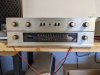
The 400 I am working on is chassis 48001 and later. As part of the restore I replaced several of the tubes in the IF and tuner section that were bad, as well as one of the 12AX7 tubes in the MPX section. I rebuilt the bias supply, did the IBAM modification, added Screen resistors and 10-ohm cathode resistors, coupling caps and a set of Hayseed Hamfest filter caps. I replaced the 330K grid resistors with 220K and bumped the coupling caps in the final stage to .1mf. I installed a set of EH 7868 tubes in the output section. The amp really plays beautifully but of course I couldn’t leave well-enough alone…….
PXL_20230420_192517111.jpg

Underside if the 400
PXL_20230420_192542823.jpg
 
Register to hide this ad
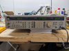
One late evening I was on the auction site and I found myself in possession of a Leader LG 3236 (S1 Version) AM/FM Signal generator. It is a very capable unit but of course the operating manual is not available in the Leader site or anywhere else that I searched. It is similar enough to some of the other Leader generators that I can find my way around the user interface. Kind of overkill for me but I figured I would grow into it so to speak.

PXL_20230419_162011683.jpg
 
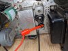
Back to the 400, the alignment instructions say to couple the signal generator output to the ungrounded shield of V2. The tube ground is riveted to the chassis so I made a loop of wire and put it around the top of V2 which the shield did not cover, set the 3237 to the IF frequency 10.7 Mz. , dial pointer to “0”, mono mode, Fluke meter to TP 3 and gave it a go. I believe I got the idea of the loop coupling from a post from Dave the master.

PXL_20230419_162038294.jpg
 
I adjusted the output of the 3236 until the speaker static started to fade out but not completely, simulating a somewhat weak station and adjusted Z1 and the top of Z2 for maximum negative reading on the Fluke. That was as far as I got as I am waiting on a set of plastic alignment tools which will arrive on Monday. In the meantime, I looked ahead to seeps 5,6 and 7 and have a few very basic questions.

PXL_20230420_015701857.jpg


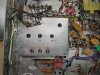
I am looking at the FM tuner box, trying to identify L1, L2, L3 and L4 as well as C3, C8 and C10. I am attaching an annotated picture of what I believe are the proper control designations. Can someone verify that my designations are correct? Thanks in advance for any assistance.

My second request is if anyone knows where I can find the manual for the Leader LG 3236 S1Version signal generator. I emailed Leader and got no response and also searched their website but the manual for this particular instrument is not available for some reason anywhere I searched for it.

.
I will continue steps 1-4 of the FM alignment on Monday after the alignment tools arrive and go forward from there hopefully!
 
If the slugs don't move easily with the alignment tools don't force them, they will crack. If stiff, I usually heat up a steel allen wrench , insert into the slug to heat it up, then try the alignment tool.
 
I just checked and my alignment tools are coming Friday so I cam move forward!
 
Good news! I received the alignment tools yesterday. I also received an email from Leader with the Manual for the LG 3236S1 and also the service manual. I am very pleased that Leader responded and came through with the manuals!
 
I spent several hours this evening following steps 1 through 4 of the fisher 400 alignment instructions. Steps 1 and 2 went well enough though to establish a peak reading I had to lower the output of the signal generator to be able to get a peak reading on the voltmeter.

When I was taking the reading across C41 the instructions state to set Z5 bottom for Maximum indication below -20v. My initial reading was over -25V and went up when I adjusted Z5. I had to again turn down the output of the signal generator to get a reading below 20V and then set Z5 for a peak reading. I am not sure that I did this correctly. I took quite a few turns to get the voltage reading, hard to believe things were that far out of kilter.

I stopped there and then tried the FM radio. It appears that it was working better before I started, more stereo stations and more separation. I sense that thinks have gone backwards instead of forward in my alignment efforts. I called it an evening and will look at things again tomorrow.

I am a little confused at this point........
 
Yes you drop the output of the siggen before each can peaking, The signal is being multiplied on each can so you want the signal to be somewhat weak when you start each can successively then peak that can. Get close to the voltages listed on each instruction. You'll drop the siggen input level on each can. This is to keep the limiter from kicking in. If Z5 is too high drop the input so you can get a voltage of NMT -20v.
 
yeah, having to wind the generator down is normal. The limiter setup in an FM tuner will automatically control gain if the level is high enough, and you'll get a wide range of rotation where the signal is maxed out. If the level is low, you'll get sharp peaks which is the "true" peak.

the problem with peak alignments though is that it doesn't guarantee the response is symmetrical, and thats what you really want for best FM performance, and FM stereo performance in particular. A simple peak align and zero the detector works just dandy in a basic mono tabletop but something thats really hi-fi you can tell when its not right. The "right" way to do this is with a sweep generator that you can view the IF response with. It should give you what is basically a flat-topped bell shape if things are right. The detector curve is roughly S shaped. If you've ever seen that piece of chrome trim on the back of a hearse, thats pretty much it.

normally unless someone has been in there before though, you shouldn't have to turn the slugs very far. When they are really whacked out, I usually center it up by doing a simple peak alignment just to get things in the neighborhood of correct, then touch it up so its right. My generator is a Sound Tech 1000a, so it works a bit differently than a typical sweep gen. What I use to center and peak things is an old HP 8640b.

one trick with all this though, you have to be sure the generator is actually outputting what you think it is. If its set to 10.7 and not giving you 10.7 it screws all of this up. I sync mine at 10mhz for no better reason than I can zero-beat it to WLW which broadcasts at 10 mhz. Bit of an old low-tech process involving a 1940s Navy radio but its plenty accurate enough. Its easy to heat offset down to a couple hertz and thats more than accurate enough for tuner alignment.

if the generator is off frequency that would also explain why the slugs had to move a fair amount.
 
Gadget; I think you mean WWV in Fort Collins (NIST station). WLW is a 700kHz AM station in Cleveland.
 
I went back out to the garage this morning and worked on Aligning the 400 again this morning. Based on Larry's recommendation in an older post I replaced C41 first thing as I did not see it during my initial restoration. It was tucked away under some other components.

I started from the beginning to make a clean start of things. I was not getting definite peaks initially, voltage was between -1 to -1.5V. I increased the generator output slightly so I got a reading of about -2V. With that setting as a baseline I was able to see more definite peaks as I tuned Z1, Z2 ,Z3 and the top of Z4. I touched things up and the tuner seemed to be working better than after my first attempt. With no antenna attached I was able to hear quite a few stations which was an improvement for sure.

I guess I am taking it in faith that the LG3236 10.7 MZ signal is accurate. I will have to try and verify that with the scope at some point.
 
PXL_20230424_152754383.jpg

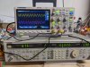
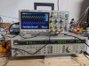
Next I went to Step 5 on the alignment instructions. I set the 3236 to 90MZ with a 400HZ modulation tome in Mono mode. I did not change the deviation to 22.5Khz, I left it at 75Khz. I used the 100K resistor to Test Point 2 with the meter and the two 120-ohm resistors to the distant antenna terminals. I plugged my scope into the right and Left tape output jacks. Yellow is left pink is right.

When I adjusted L4, I found a definite sharp peak after moving the slug only slightly. I moved L3 and L2 but could not detect any voltage variance so I just left them set where I found them. The dial indicator on the 400 was spot-on at 90 MZ.
 
PXL_20230424_153326719.jpg

I went to Step 6 next and set the generator to 106MZ, same modulation settings. I adjusted C10, C8, and C3 per the instructions. C10 had a slight effect on the voltage read and I peaked it. C8 and C3 had no discernible effect on the voltage so I left them set as I had found them. The dial on the 400 was off slightly from 106MZ but not enough to concern me at this point.
 
PXL_20230424_153641210.jpg

I proceeded to Step 7 and set the generator to 98MZ. I adjusted L1 for a peak voltage reading which ended up being no change in setting. The voltage did not vary when I adjusted L1 so I left it set where I found it.
 
One thing I should have mentioned earlier is that during Step 2 when I adjusted Z5 bottom I got very little reading on the tuning eye. There was peak but it was very low. I tried turning up the generator output level but I had very little effect on the tuning eye.

I noticed this also when I was using the receiver with an antenna. In stereo mode the tuning eye behaved as it should but in mono mode there was no indication of signal strength at all even though the radio was functioning well. I will have to pursue that issue going forward.
 
PXL_20230424_191207599.jpg


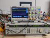
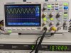
Sanity check, hooked output of the signal generator to verify that 10.7 MZ signal frequency was accurate. Looks good fortunately!
 
Back
Top Bottom