• The move to the new server is done. There are some software and database maintenance updates in process. This has us passing the hat around to help out. We appreciate any donations. Seriously, even a dollar helps. The payment page may be found here - https://www.audiokarma.org/support.html

More Fisher 400 FM Alignment Questions

R228, which is also R209 on some schematics, is a 1 Meg resistor that appears between the output side of C210, and ground. The numbering inconsistencies is because in early versions of the MPX-65, the ring diode detectors were made up of individual diodes, later made up as two complete diode assemblies, and finally as assemblies that also included the 33K isolation resistors within the assemblies. This, and the fact that there was also some variations as to how the indicator output was configured meant that the numbering of the resistors on the schematic changed over the course of the 400's production.

I hope this helps!

Dave

Your response was a big help Dave, thanks for the assist! I found the proper point to attach the DVM to monitor AC voltage. The Blue test lead is the positive lead for the DVM for Step 1 of the alignment procedure. The Red lead is the lead that is injecting the 80Khz test signal from the audio signal generator. I adjusted L100 with the alignment tool and the AC voltage never really changed at all, kind of drifted around, never really stabilizing at all. Stopping and 80Khz signal and starting it had no effect on the voltage at all.

The instructions are pretty vague as far as what switch settings on the selector switch should be used. I tried FM mono FM auto and FM stereo. settings did nit seem to make any difference though in FM Mono mode all sound from the speakers was muted when I applied the 80Khz signal.

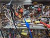
I am attaching pictures of my setup here as a sanity check. Please take a look and confirm I have things set up correctly.

PXL_20230517_173810579.jpg

PXL_20230517_173826231.jpg
 
Where are you injecting the test signal? It doesn’t appear you are injecting it at the correct point and, the injection point needs to be disconnected from the output of the ratio detector when injecting the test signals. It is normally a black lead that connects the output of the ratio detector circuit to the input of the MPX-65 sub-chassis.

Dave
 
Dave, thanks for your prompt answer, found the black lead and moved the signal injection signal to that point. Things are behaving better now and through serendipity the coil setting was very close to the mark. It is a bit late here and also kind of warm in the garage here in Florida so I will pursue things tomorrow. I read that for Step 1 I should not have disconnected from the ratio detector, that was done starting with step 2. Fisher alignment directions are challenging....:crazy:

I will disconnect the black wire tomorrow and go forward from there. Thanks for your help.

Rich
 
If your signal generator has a low enough output impedance to drive the MPX input with the ratio detector circuit still connected, then that's fine. Some generators can't however, so I always recommend that it be disconnected as a safeguard. Fisher aligned the MPX sub-chassis on its own production line before it was installed in the receiver.

Dave
 
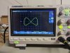
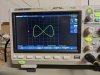
I made some progress today. I was able to get as far as the lissajous pattern pretty clean on the scope. I have never used the scope in "X-Y" mode before so it probably took longer than it should have. The signal generator I am using does not have a provision to adjust the pilot output level as required by the alignment procedure. I will have to experiment with using additional resistance in series with the generator input to Lug #1. I found that if I put the 400 in phono mode it effectively negated the "interference" that the FM tuner would normally feed into the multiplexor so I left it connected.

I have a ways to go but I am having fun learning more about the Fisher 400 and my test equipment. The 19Khz and 38Khz signals are spot on.

PXL_20230518_204253301.jpg

PXL_20230518_204235851.jpg
 
I worked on the 400 MPX alignment some more today. The LG 3236 did not have a means to modulate the 19Khz Pilot sub-carrier. I am not sure what Fisher exactly means by that as I thought the 19Khz. tone was just a marker indicating a stereo signal was present in the FM signal.

What I ended up doing to perform steps 5 -15 with the RF output of the 3236 attached to the Antenna Terminals of the 400. I found a spot on the dial that was relatively quiet, (around 90Mhz) and set the generator output to the frequency and the output amplitude to about 60DB which was enough to quiet the background noise but weak enough not to trigger any limiting action in the FM Tuner section feeding the MPX unit.

I was able to adjust the Z100 top for max AC voltage at 1Khz and R215 for max separation. What I found while adjusting Z100 and R215 is there seemed to be some interaction between the two controls. The best separation seemed to be obtained when Z100 was a bit off the Maximum AC reading in combination with adjusting R215.

There was definitely less separation at 8 Khz. as indicated in the test procedure.

Things seemed to be lining up well with my somewhat unorthodox alignment procedure. I was looking at things and then realized that the left and Right Channels were reversed................
 
I then remembered something that Gadget mentioned in a previous post:

I think its the 38kc transformer, but one of them will have 2 peaks, and if you get the wrong peak the channels end up backwards.

I figured at this point I had nothing to lose so I adjusted Z101 while watching the scope outputs of the left and right audio signals from the output lugs of the MPX unit while driving only the left channel. The signals gradually shifted from the Left to both and then to the right channel. Completely unorthodox but the end result was that the left and right channels were where oriented correctly and and the separation was quite good.

I probably should go back and start from Step 2 again to tweak everything more systematically but the end result is that the 400 FM stereo has good separation and sounds very nice.

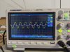
Here is a picture of the 1Khz signal with only the left channel being driven. The left is the yellow trace and the right is the pinkish trace:

PXL_20230519_161136027.jpg

Here is the scope shot with just the right channel being driven:

PXL_20230519_161215786.jpg


Not perfection separation-wise but not too bad either.

I may make another pass at the MPX alignment but I am pretty happy with things as they stand.

We are packing to head to Michigan this Wednesday for the summer so bench time is getting short. The 400 is staying behind in Florida so if I do not get to it shortly it will have to wait until fall for any further fiddling!
 
Thanks to everyone for their support during me efforts in this thread. It is one of the reasons I like the Fisher forum so much, I would never have gotten this far without the insights everyone provided. They saved me a lot of time and frustration!

:thumbsup::thumbsup::thumbsup:
 
If I may, let me offer a few things to ponder during your summer break:

1. The 19 kHz signal is an extremely important component of the total FM MPX Stereo composite signal broadcast by a stereo station -- necessary for much more than just to provide a trigger for indicating reception of a stereo station. That it can be used to perform that function falls in the same category as the fact that horse manure also makes for a good fertilizer. It's a nice byproduct which can be used for that purpose, but hardly reason for its existence! The singular primary purpose of the 19 kHz pilot signal is to either: (1) provide a signal that can be doubled in the decoder to 38 kHz or (2) provide for the proper triggering of an onboard free running 38 kHz oscillator in the decoder. Either way, the generation of a 38 kHz signal of the proper phase is required for the detection of the 38 kHz double side-band suppressed carrier "stereo information" channel, which is also part of the total composite signal broadcast by the station. Now any 38 kHz signal could detect the stereo information channel. But because the L-R signal it contains must be perfectly aligned time wise with the L+R signal broadcast in the main channel of the total composite signal, the timing (or phase) of the 38 kHz signal is crucially important in achieving maximum separation -- which under ideal conditions can approach 40 db at 1 kHz. 30 db of separation (L to R and R to L) is routinely possible, while the Fisher specification of 35 db is also quite possible when all is operating properly. These figures are for the condition of a FM MPX Stereo composite test signal broadcast into any Fisher component with built in MPX adapter. If the timing of the regenerated 38 kHz carrier is off by just a few degrees, then separation suffers quite significantly. The Fisher design employs a free running onboard 38 kHz oscillator (part of V101), with the 19 kHz pilot signal providing the proper timing of the oscillator to achieve optimum separation. It is also used to trigger the stereo indicator on those models employing such an indicator.

2. While your scope surely showing notable separation between your L and R signals, overall it is still considered quite poor compared to proper operation of the decoder. Based on the difference in amplitude of the two signals (assuming both scope channels are set for the same sensitivity), I would suggest that the separation displayed is on the order of 14-17 db, or about half of what it should be based on db measurements.

3. I'm not sure what you mean by the Fisher instructions requiring modulation the 19 kHz pilot signal. The pilot signal is the pilot signal, and is never modulated by anything. It's used for the functions as discussed in #1 above. Now, the main channel and 38 kHz sub-channel elements of the composite signal are certainly modulated by the material being broadcast, but the pilot signal is a constant, with its value required by the FCC to be specifically within the limits of 8-10% of the total composite signal modulation.

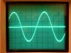
4. I've included a pic of the FM MPX Stereo 1 kHz L only test signal broadcast into my Fisher 202-T tuner/preamp after it was modified and had a Fisher type WX MPX decoder sub-chassis installed for your reference. The sine wave is of course the left channel, while the line through it is the right. A R only test signal looks identical, so I only provided the one pic. The actual separation produced when this pic was taken was measured to be 38 db. The R to L separation was slightly better at a measured 39 db. You can use this as an optimum example to shoot for in your work.

My comments are hardly meant to be critical of your work. I know this effort is as much of a learning exercise for you as anything which is great, because you learn the most by doing -- and you're making very good progress in doing just that. I just wanted to establish where the goal post is so you'll know where you currently are, and what it looks like when you reach it!

I hope this helps when you return to your project!

Dave
E3AAB608-CE2B-4C67-A287-07C76B1EE6DA.jpeg
 
Dave,

Thanks for your thoughtful reply, it definitely helps clarify things for me. I definitely do not take it as criticism, more like guidance from the professor to a student.

I did in fact have another go at aligning the 400 yesterday. I was re-reading the instructions for the alignment and realized in step 5 I missed Note 3 in my previous efforts. It talks about monitoring T.S.P. 101 while adjusting the top of Z100 for maximum audio on the channel "A" output lug.

I repeated the alignment procedure this time adjusting Z100 and monitoring the voltage on T.S.P. 101. I spent quite a bit of time adjusting the top of Z100 and then re-adjusting the bottom to max out the negative voltage on T.S.P. 101. I covered the entire range on both the top and bottom to make sure I covered all of the potential combinations. At one point the left and right channels reversed but eventually I found the best combination of settings for both adjustments that provided the most separation with the highest voltage at T.S.P 101. Note 3 calls for a voltage greater than -9V . The best I could achieve was -5.2V. I am assuming the instruction implied a greater negative voltage. Step 2 specifies adjusting Z100 top and bottom for maximum voltage initially. Assume they meant maximum negative voltage even though that was not stated.

At the end of the day I ended up in roughly the same place as I was previously with perhaps a slight improvement in separation but not where it ultimately should be as you indicated. I guess the next steps will be testing individual components on the MPX sub-chassis to see of anything is amiss. A good Fall Florida project!

Thanks again,
Rich
 
Back
Top Bottom