• The move to the new server is done. There are some software and database maintenance updates in process. This has us passing the hat around to help out. We appreciate any donations. Seriously, even a dollar helps. The payment page may be found here - https://www.audiokarma.org/support.html

More Fisher 400 FM Alignment Questions

I hooked up a dipole antennas to the 400 this evening and FM reception is much improved after my second pass at alignment. I still have to figure out why the tuning eye is not working when the 400 is set to Mono FM.

I am reviewing the alignment procedure for the Multiplex section now but am not sure I will attempt it. Stereo reception is quite good as things stand so I may just leave things be in that section for the moment.
 
If you're getting decent Stereo reception, I'd leave it. Fisher aligned the MPX separately from the receivers and installed them.
 
Gadget; I think you mean WWV in Fort Collins (NIST station). WLW is a 700kHz AM station in Cleveland.


err, yeah, that. One of those things with two W's in it.


if the eye works in stereo and you have ALC voltage, I'd be looking at the mode switch. The grid of the eye should route through that switch to flip it from the ALC line to the MPX unit.

upload_2023-4-25_9-37-15.png

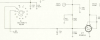
is that chunk of the schematic. D is from the MPX unit. ALC line is TP2, so if that voltage reads, the connection appears to go through R23.
 
Last edited:
I did some more testing this morning to check on how the 400 was performing in stereo mode. I also have to get more familiar with the interface and nomenclature using the 3236 generator as some of the settings in stereo mode seem to behave inconsistently but that could definitely be user error on my part.

I fed the output of the signal generator into the antenna terminals of the 400 through the resistors as specified during the alignment. After experimenting with various settings I had the 3236 in stereo FM Mode. I adjusted the separation pot on top of the MPX chassis for the "flattest" non-driven channel trace I could get. I am attaching traces for the left (Yellow) and right (Pink) channels with the separation control adjusted for the best separation without distortion. If I advanced the control further the non-driven channel's signal went "flatter" but there was more distortion so I went for the most separation without discernible distortion at 1Kz. I was hoping for better but guess this is the best I can get without digging in deeper into sligning the MPX unit. Funny, when playing music the separation appears pretty decent!

Right Channel
PXL_20230425_155849060.jpg

Left Channel
PXL_20230425_155802000.jpg
 
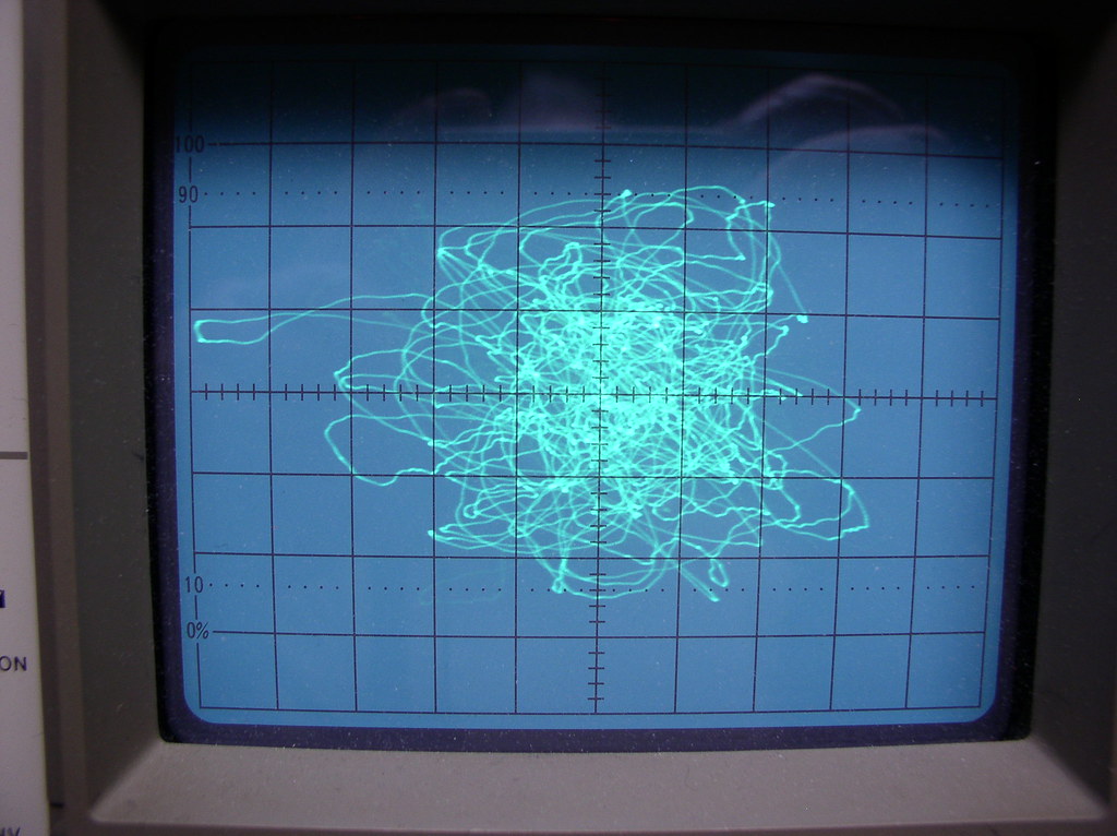
I can't find @fred soop s visual description of it but putting one channel of the 400, on the horizontal channel of the scope, and the 400's other channel on the vertical scope channel, and playing a stereo station will give you a jumble described as Beethoven's brain on Drugs. Never played with mpx so not sure how he adjusts it.
 
Fisher tuners and receivers are routinely capable of producing 30 db of separation both L to R and R to L, and over 35 db with careful attention to balance and adjustment, as measured at 1 kHz, and broadcast into the unit.

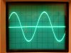
One of the easiest ways to visually check for good separation when a MPX generator is available is to connect the output of each channel to the inputs of a dual trace scope, and then superimpose the two traces on top of each other. Operating properly, the resulting image should look like that shown in the pic provided (either channel being driven individually) as developed at the output of my 202T tuner/preamp (MPX test signal broadcast into it), with the driven channel represented by the sine wave, and the base line through the center of it the un-driven one. Such a visual indication will invariably produce excellent measured and audible separation.

Dave

E3AAB608-CE2B-4C67-A287-07C76B1EE6DA.jpeg
 
I can't find @fred soop s visual description of it but putting one channel of the 400, on the horizontal channel of the scope, and the 400's other channel on the vertical scope channel, and playing a stereo station will give you a jumble described as Beethoven's brain on Drugs. Never played with mpx so not sure how he adjusts it.

Here it is. Scope in X-Y mode with audio from one channel on the X axis, the other on Y. Signal can be taken from any point, even the speaker terminals. Find a classical station with a full orchestra. Never done anything on tube units but the SS units basically need to have all the multiplex coils set for maximum output at the test point and the separation adjustment then set for the maximum fuzz ball.

Be aware that if the separation pot is advanced too far, it will sound like good separation but the channels will be out of phase and something won't sound quite right. Start at no separation and advance the control. Separation will max, then almost null, then max again but out of phase,

13727611295_d1f2a4bca1_b.jpg
 
Last edited:
Dave, thanks for your suggestion, makes more sense than using the vertical offset I used in the previous pictures. I was in the garage for several hours tonight experimenting around with the 400, the signal generator and the scope. I came away more confused than when I started which is not unusual for me during my learning curve.

I came away with a few things, the FM stereo signal is less noisy when the selector is set to "FM Stereo Filter" rather than "FM Stereo"

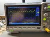
I will attach two new pictures following Dave's suggestion shown above. They are a little blurry, the camera focused on the clutter behind the scope rather than the scope and I didn't notice that until I called it an evening. The pictures are with the right channel driven at 1Kz. As can be seen things are off just a bit........

FM Stereo Filter selected:
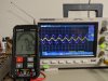
PXL_20230426_003953806.jpg

FM Stereo Selected:
PXL_20230426_003945942.jpg

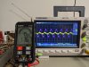
The A/C like Voltmeter is in the photo because I observed that the Stereo Separation appeared to get worse as the 400 warmed up. It was better when I initially turned it on at the beginning of my testing.

When I lower the A/C voltage the separation improves a bit but is still a long way from where it should be. The B+ voltages in the 400 output section were spot-on. I will measure the voltages in the MPX and IF sections to confirm they are where they should be.

Based on what I have been reading in all the threads on the 400 MPX alignment I have decided to go back to step 1 in the Alignment instructions and re-align the IF sections. I am more familiar with the operation of the Signal Generator now as a good IF alignment is critical to the MPX section working as it should as I have read repeatedly. I performed steps 5 through 7 with the generator set to 75kz deviation which no doubt affected the results of those steps of the alignment.

We will see what tomorrow brings, thanks to everyone for their suggestions, I will post the results of my next attempt at alignment in the next day or so!

 
Fred, Just saw your post, will give your suggestion a go as I am definitely seeing phase shifts in the scope during my testing. Thanks!
 
A brief update, I checked all of the voltages in the IF and Output sections at 120V line voltage and everything was within tolerances. Did not do anything further as "the one who must be obeyed" (Larry's term :)) thought we should go out for dinner which actually was a great idea, I didn't have to cook! More to come tomorrow........
 
I didn't originate "SWMBO". But it was really popular on the boards back in the mid teens.
 
I think the SWMBO term comes from the old British show "Rumpole of the Bailey". At least that's the first place I heard it.
 
Got sidetracked a bit but I resumed my alignment efforts Saturday. I started from Square one and went through Steps 1 through four being careful to adjust the signal generator output to keep the measured voltage around -2V. I went through steps 1-2 repeatedly and I definitely identified more definite peaks by tweaking the generator output and re-adjusting Z1-Z4 Top. I was still having problems getting Tuning indicator to respond to setting Z4 Bottom. I continued on to steps 3 and 4 and then performed steps 5 through 7 with the proper signal generator settings this time (22.5 Khz. deviation and 400 cps tone). I went back over everything several times and found that I was able to adjust Z4 bottom to yield a decent reading on the tuning indicator.

I went over everything again and things look much better now. The Tuning indicator is working as it should in mono mode which I am pleased about. The tuner is more sensitive and the Tuning indicator is working properly on Mono mode. I takes a few minutes for the indicator to work properly in mono on cold start-up but overall I am pleased with things at this point.
 
I also did some further experimentation with the FM stereo settings. Using the generator and the scope I achieved approximately the same results I achieved previously. The one observation I made is that the left and right channels appear to be reversed. When I configure the generator for left output only I see the output on the right trace and vice-versa.

Since the LG-3236 generator is a new acquisition for me I wondered if the generator itself might be having issues.

Yesterday I performed an alignment on a Marantz 2325 receiver I recently received back. (I know HERESY in a Fisher forum!)
I went through the alignment procedure for the 2325 and everything worked as it should. What I conformed from this is that the left and right outputs in the MPX output of the LG-3236 correctly correspond with the left and right channel outputs on the 2325. The disabled channel was a flat line on the scope and the driven channel showed a clean sine wave. I should have taken a picture but unfortunately I did not.

I am reviewing the alignment instructions for the Fisher MPX unit. I have the required test equipment, just have to find the setting to put my scope in X-Y mode for the Lissajous pattern.

I think I may try to start the alignment procedure for the MPX unit and If things seem to be behaving initially go through the entire procedure as my MPX unit in a bit out of kilter for sure. Funny, it doesn't sound bad, though compared to the 2325 it is definitely needing some help.

Wish Me luck!
 
I think its the 38kc transformer, but one of them will have 2 peaks, and if you get the wrong peak the channels end up backwards.
 
Hi

Just purchased a leader lg3236 and look forward to learning more about it. Nice work.

Thanks for sharing. If you’re willing to email me those manuals that’d be great.
 
I think its the 38kc transformer, but one of them will have 2 peaks, and if you get the wrong peak the channels end up backwards.

Thanks for the information, I am going to get back to the 400 this week. I will see how things go.....
 
I was looking to start aligning the MPX section of the 400 today. I was reading the alignment instructions which look like they were lifted directly from the Fisher KM-60 tuner service manual. Step 1 of the instructions refers to the junction between C210 and R228 as the place to attach a VTVM. I assume the negative lead should go to ground. The problem is I cannot find a R228 on the MPX schematic. Am I just missing it?

upload_2023-5-15_1-9-58.png

upload_2023-5-15_1-15-18.png


The instructions also refer to the MPX test jack which is present in the KM-60 tuner but not on the 400. I can work around that but not the R228 reference.
Perhaps some more experienced hands can help me out here....:(:(
 
R228, which is also R209 on some schematics, is a 1 Meg resistor that appears between the output side of C210, and ground. The numbering inconsistencies is because in early versions of the MPX-65, the ring diode detectors were made up of individual diodes, later made up as two complete diode assemblies, and finally as assemblies that also included the 33K isolation resistors within the assemblies. This, and the fact that there was also some variations as to how the indicator output was configured meant that the numbering of the resistors on the schematic changed over the course of the 400's production.

I hope this helps!

Dave
 
Back
Top Bottom