• The move to the new server is done. There are some software and database maintenance updates in process. This has us passing the hat around to help out. We appreciate any donations. Seriously, even a dollar helps. The payment page may be found here - https://www.audiokarma.org/support.html

MR80 display ranging

Hello Gregory

Yes all should be changed and the both bipolar are often bad ! you can see it on the surface of their "body" !
Your pictures are clear !
be carefull with the capacitor replacement because one is 100V insolated !
I will post a picture of a damaged PDB because of bad cap not changed in due time ...
 
Yes all should be changed and the both bipolar are often bad ! you can see it on the surface of their "body" ! Your pictures are clear ! be carefull with the capacitor replacement because one is 100V insolated ! I will post a picture of a damaged PDB because of bad cap not changed in due time...
There is trouble with the camera shooting in existing light on the PCBs. It tries to set a high ISO (thinking "not enough light") and the resolution takes a hit. Plus.. the photo editing software is suggesting a HIGH `sharpen´ coeff. That's why they look ragged. I'm usually backing off the filter to less sharpening effect. Maybe better to get out the Canon A590 which takes GREAT close-in photos. This is example of A590 and with old version of photo process software. It looks more like the real light and doesn't try to make "outdoor" conditions.

100 Volt Cap

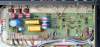
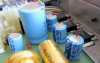
Beside all that, have another couple of photos to present from yesterday. Here is the view of PCB underneath chassis with shielded cables running to NP caps, LDR muting devices and proximity to output jacks. Is 100V cap you describe like so?

MR80_PS-output_board.jpg


And another view of the PCB you have already described.

PS_board_caps_2.jpg

Will be sure not to misconnect the three-prongers. :D


-Greg
 
Last edited:
Just in this one picture the clariix LDRs, ROE sealed NP caps and German axial caps all have a history of issues, some early, some late, but all need attention now that these units are approaching their 30th birthday.
 
Hello Gregory

1) YES ! this is this capacitor !
2) as promised here are some pictures of a power supply PCB coming from an MR80 came too late for capacitors replacement :thumbsdn:
 
Last edited:
1) YES ! this is this capacitor !
2) as promised here are some pictures of a power supply PCB coming from an MR80 came too late for capacitors replacement.

Ooh.. that's built-in fuse protection!! :rflmao::rflmao:

All joking aside, that PCB trace got hot all right, and you've done a good job restoring it. A lot can be done with solder if you have a few helper tools. My 25-watt Weller from the 70's (when I was a lad) is still in use today, and has the original tip!

For some reason, there is difficulty ordering caps.. going from a caps list (noted from schematic and Parts List) to the `cart´ at the vendors site. Also working the order list in with caps on hand.

Today I should be able to get into the MR80 chassis and measure the axial caps.. to make decisions what voltage the NEW caps will have. It depends on physical size and space on the PCB.


-Gregory
 
Last edited:
Came up with a table of MR80 Power Supply caps and their physical sizes.
Code:
            Capacitor     uF    Volts    length    dia  (in)
Power Supply board #1
              C701        4700     16     1.51    0.83
              C702        2200     16     1.12    0.63
              C703        1000     40     1.12    0.63
              C704         470     40     1.22    0.47

Power Supply board #2
              C708         220    100     1.12    0.63
              C714         470     40     1.22    0.47

                                height    dia  (in)
              C710          22    160     1.03    0.63

Goes to show how fast things are happening around here. As always, check your hardware and schematic to confirm.


-Greg
 
Last edited:
Came up with a table of MR80 Power Supply caps and their physical sizes.
Code:
            Capacitor     uF    Volts    length    dia  (in)
Power Supply board #1
              C701        4700     16     1.51    0.83
              C702        2200     16     1.12    0.63
              C703        1000     40     1.12    0.63
              C704         470     40     1.22    0.47

Power Supply board #2
              C708         220    100     1.12    0.63
              C714         470     40     1.22    0.47

                                height    dia  (in)
              C710          22    160     1.03    0.63


Got the order placed with Mouser this afternoon with only 5 weeks delay.
Code:
647-TVX1E472MCD     4700uF    25V      C701        5.47 ea

647-TVX1E222MCD     2200uF    25V      C702        3.71 ea

647-TVX1H102MCD     1000uF    50V      C703        3.59 ea

647-TVX1H471MCD      470uF    50V      C704, 714   1.39 ea

647-TVX2A221MCD      220uF    100V     C708        2.17 ea

These are Nichicon Standard Aluminum Electrolytic VX series. Hope that's ok!


-Greg
 
Last edited:
There seems to be problems with the MR80 Schematic

In the photo below, connected to ICs 701 thru 703? the caps are incorrectly labeled on the Schematic??

MR80_PS_PCB_256.png

Here are the discrepancies

1. C711 on schematic is 100uF, 40V (for +30Vline) but on PCB it's 16V??

2. C713 on schematic is 2200uF, 16V (for -15V line) but the value on board is 220uF, plus the polarization is reversed?

3. Where is the other half of Power Supply PCB <11> on schematic with two 1000uF, 10V caps?


Here's another view

MR80_PS_caps.gif

Looks like ordering caps will be delayed another day?


-Greg
 
Last edited:
#3? They are part of headphone amp.

As for #1 and 2 who knows, mistakes in the schematics happen all the time, just need to correct them as you go. Joe wrote these 30 years ago, makes no sense to beat up on him now.
 
Last edited:
#3? They are part of headphone amp.

I posted a photo above with three low-profile caps on the Voltage Regs? The 100uF is on a +30V line? and the 220uF is designated 2200uf on the schematic? and for -15V (polarity?)


-Gregory
 
My at hand service manual shows C711 to be a axial cap not a radial.

Short form schematic C713 is obviously a typo 2200mfd makes no sense; 220mfd does and is stated as such in actual service manual.
 
Last edited:
My at hand service manual shows C711 to be a axial cap not a radial. Short form schematic C713 is obviously a typo 2200mfd makes no sense; 220mfd does and is stated as such in actual service manual.

That means it should be standing on end? I have no Parts List, just schematic Sheet 1 and 2 of 2.

The 1000uF, 10V caps are C810, 811 in a tiny schematic section below PCB <5> which is fine.

C713 is 220uF, 16V (I believe that) but is shown on he schematic with + side connected to the -15V output of the volt-reg.

The other issue is.. C711 is 100uF, 40V on the +30V volt-regu output, however the factory cap is only 16V. Not good! :nono:


-Gregory
 
Last edited:
From what I can see in the picture the IC is a 13 or 15 volt regulator.

Your power supply does not conform to outline in service manual as I can see it. Service manual is a notebook, 120++ pages
 
Last edited:
From what I can see in the picture the IC is a 13 or 15 volt regulator. Your power supply does not conform to outline in service manual as I can see it. Service manual is a notebook, 120++ pages

What IC? what doesn't conform? That's what the questions in this thread are asking. I've already stated that C711 is a 16V cap on a 30V PS line.

There are three ICs that look like voltage regulators.. IC701, 702, 703 @ +30V, +15V, -15V output.

I know the service manual is a large volume but I don't have it.


-Gregory
 
Last edited:

I think what's happening is


C711 (100uF near the camera) is the wrong voltage (should be 40 or 50V) and C713 (220uF on the far end of the photo) is soldered in backward?

MR80_PS_caps_256.png


-Greg
 
Last edited:
I know the service manual is a large volume but I don't have it.

Greg, I have service manuals for every piece of McIntosh equipment I own and for some that I don't. I am going to get a MR80 so I ordered a service manual last week. I recommend that everyone get service manuals for everything McIntosh that they own even if they will never service their own units. When a piece needs service, the tech will appreciate the service manual if he doesn't have one will make the repair just that much quicker.

If I didn't have the MC2600 service manual, I would have never been able to upgrade my MC2500 amps.

Owning the service manual for the MR80 is a wise investment.

Richard
 
Hello Gregory

Sorry I don't live in front of my computer and don't go everyday on AK ! when you need urgent information send me one MP .

1) do not trust what you have as "service manual" the original MR80 binder is 99% sure with some mistake but you can trust it
2) see my picture about the PCB and the page of the parts list and you will see that there is nothing drastic there !
You have to remember also that the big MR80 service manual do not include everything ....and all improvement made on the last unit manufactured (serial number CK 39...)
I have refixed 5 MR80 this month and some do not have the same power supply PCB factory number ! the last one I have is stamped 045682 , yours is probably with different numbers (the last 3 digit) 045...
 
Last edited:
Hello Gregory, Sorry I don't live in front of my computer and don't go everyday on AK ! when you need urgent information send me one MP.

1) do not trust what you have as "service manual" the original MR80 binder is 99% sure with some mistake but you can trust it

2) see my picture about the PCB and the page of the parts list and you will see that there is nothing drastic there !

You have to remember also that the big MR80 service manual do not include everything ....and all improvement made on the last unit manufactured (serial number CK 39...) I have refixed 5 MR80 this month and some do not have the same power supply PCB factory number ! the last one I have is stamped 045682 , yours is probably with different numbers (the last 3 digit) 045..

Hey that's GREAT.. merci buckets!!

And you have a stack of five high-end tuners there. Astounding!


Edit: thanks to your PCB diagram, I see the schematic here has a few mistakes. The pins on IC703 are labeled wrong, so the cap in not in backward. The schematic has C713 designated 2200uF, should be 220uF and the polarity reversed.


-Gregory
 
Last edited:
Back
Top Bottom