• The move to the new server is done. There are some software and database maintenance updates in process. This has us passing the hat around to help out. We appreciate any donations. Seriously, even a dollar helps. The payment page may be found here - https://www.audiokarma.org/support.html

MR80 display ranging

Six big axial caps for the power supply came in today from Mouser.

I ordered Nich VX series: http://nichicon-us.com/english/products/pdfs/e-vx.pdf

Hope those are ok. If not, then please advise. These new caps should be superior to what's in there now. They are dark blue general purpose aluminum electrolytics and fit nicely in the original form factor, even at the next higher voltage rating. Possibly the biggest Mouser cap order will come in tomorrow. After that.. another large order of Nich caps from Hand Made will arrive. There are enough in total to recap four or five pieces of Mc gear. The old 70's stuff is finally getting some attention. :yes:

Probably best to start a new thread on the power supply recap: http://www.audiokarma.org/forums/showthread.php?t=492147
then pull it back into the MR80 display ranging topic.


-Gregory
 
Last edited:
Tuner still malfunctioning

The MR 80 is back together after double and triple checking the cap polarities, etc. Started up and it was drawing 26 Watts from AC line. All was looking good at 91.9 MHz on the display. Unfortunately after ~30 seconds, the display started ranging again with "tink, tink, tink" sound of the 100 MHz digit blanking relay. :(

Well.. it's got a recapped power supply which is good (for 30 years or so.)


What next? Time to buy a scope perhaps.


-Gregory
 
Last edited:
I would measure all the supply voltages. A scope would be good. A service manual for the MR80 is another must.
Measuring voltages would be an easy exercise. I have a Service Manual that Glenn sent via USPS, thanks man!

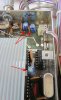
There are TWO caps on PCB <8> "Control Logic.. and Tuning" that are filters? C313 & C319. That board has some strict ESD and contamination from finger prints guidelines which are spelled out in the SM.


Have a look at the PCB <8> below in the front-right quadrant:

* C313, a dark RED 10uF NP toward the back that's on the Tuning Correction Voltage line.

* C319, a larger BLUE electrolytic toward the front that filters the +15 rail for ALL the ICs.
​

MR80_new_PS.jpg


If measuring voltages and replace a few more caps doesn't do the trick, then a scope will be needed. It should be sent off for a good alignment at this age!


-Greg
 
Last edited:
Well, I'm just happy I bought a MR80 which has been fully done by Terry.
Looks like they can be a bit tricky to diagnose and repair when the logic starts playing up.
I wonder if any replacements for those digital chips are available?
Hopefully that is not the problem....
 
You are down to needing a Scope to check the level of the signal going to the counter assembly, possibly the input buffer in the counter is weak or the signal low from the RF module.
 
I wonder if any replacements for those digital chips are available?
Hopefully that is not the problem....

Yes all the parts are available.

To be honest, I prefer troubleshooting a digital circuits opposed to a to a high impedance very low signal RF analog circuits. It takes some special considerations when dealing with low level mixers, etc.

If I were you I would send it to Terry. He will go through the whole thing and it will perform better than new.

At this point in time it could be anything that is wrong. From an IC to a weak transistor to a bypass cap.

There is more to it than just sticking a scope probe onto an IC. There are some things that show up that are important and a lot of things that don't mean anything. Learning the difference between the two takes time.
 
Yes all the parts are available.

To be honest, I prefer troubleshooting a digital circuits opposed to a to a high impedance very low signal RF analog circuits. It takes some special considerations when dealing with low level mixers, etc.

If I were you I would send it to Terry. He will go through the whole thing and it will perform better than new.

At this point in time it could be anything that is wrong. From an IC to a weak transistor to a bypass cap.

There is more to it than just sticking a scope probe onto an IC. There are some things that show up that are important and a lot of things that don't mean anything. Learning the difference between the two takes time.

Good to know they are still available.......

Also, good advice Rich, indeed all well and good having a scope (not that Gregory was suggesting he was getting one as I understand it), but you do have to have an understanding of the circuit you are working on and how to use a scope, what to look for and what not to worry about.....you really have to know your stuff getting into this area of the MR80....

It seems from my observations with the MR80, that if they are anything less than perfect condition, aligned, and serviced by a resident guru, they can be trouble.....

My advice is to just send it in to Terry and be done with it, servicing diagnosing and repairing something like this requires skill knowledge and experience you simply cannot learn in a forum on the internet, it takes years to get to this level....
 
A good scope is essential. I prefer the older Tektronix like the 465. They are repairable, reliable and not expensive.
 
All good advise and inputs, thanks.

Looking over the schematic, there is no reed relay that blanks the 100 MHz digit directly. It's done in hardware.. with gates etc. Speaking of relays.. I see K301 thru K304 on PCB <8> which are: SCAN STOP/START (2X), SCAN RUN/STOP, and SCAN SPEED UP. My concern... the "tinking" relay was taking a beating!! It's cycling at ~2 CPS.

I could find out WHICH relay is activating with a stethoscope (or an oscilloscope) but probably not a big deal. That would be a clue.

Why bring this up? is it ok for that relay to be cycling continuously while diagnosing? which could be an hour? Will it degrade? Now long could the relay cycle (in hours) before it would fail?


More re-capping

Thinking of replacing the electrolytic caps on PCB <8> while it's here with cover open. Any other things I could do before a diagnostic and alignment service? Maybe someone else would like to take on this project. I might throw in a Stereo Probe FM Yagi. :scratch2:


Another lunched screw

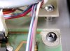
Decided to buy ALL new SS #4-40 screws for the PCBs underneath.. eight in all. While changing them out, the Phillips slot of rear screw for PCB <8> was lunched in the "tighten" direction. Then in got lunched slightly in the "loosen" direction after I tried to remove it. A LOT of downward force was needed to SNAP it free (scary!!) Many of these PCB screws are VERY tight and make a "snap" sound when they break free.. that is after applying a LOT of torque!! Below is the lunched screw.

I was concerned that it was STUCK and contemplating the possibility of using vise-grips of worse.. a drill bit to remove it. :yikes:

MR80_PCB_screw.jpg


The screw in the PCB behind is one of the new 4-40 stainless. I believe what happens over the years is the threads cease in the aluminum? standoffs. The metal composition of these screws is too soft, making the problem worse. What are we talkin' here? 30 years? It's got to go another 20 or 30 years! That is unless some BOZO...............


-Gregory
 
Last edited:
A good scope is essential. I prefer the older Tektronix like the 465. They are repairable, reliable and not expensive.

I've got an old 475 and a 465 but they are past their reliable service life now and although I liked the feel of them I am now using a Tek 2465 350mhz 4ch, the last bastion of analogue scopes......
I cant afford to have something older and unreliable since I use one nearly every day....
 
Hello Greg

You can't dammage a screw like this one is you use the right screw driver (whatever it is tight ). Many people use cruciform type for posidriv screws and this is not a good idea ! cruciform type should be use for cruciform and posidriv screw driver for posidrive screws nothing else ! that's it !
Regarding the color of the screws I don't think that they are original type because they are black . Normaly and if I good remember , all the screws (big) for all pcb's are not black (ground contact will not be good enough with black screws much better to use "silver "type , contact will not be corroded ). Only the small one are black (power supply board on the left and pcb with the AUDIO output connectors (long pcb) .
The screws for the IF cover are not black too and they are amagnetic .
Regarding the recap procedure , good job but you did not change the 3 in the frequency counter ? If I good remember there is 3 cap of 22MF /6V radial (C103/C104/C124)
 
Last edited:
Hello Greg

You can't dammage a screw like this one is you use the right screw driver (whatever it is tight ). Many people use cruciform type for posidriv screws and this is not a good idea ! cruciform type should be use for cruciform and posidriv screw driver for posidrive screws nothing else

Just to make matters worse there is a Japanese standard and a USA standard for phillips head screws.

Usually a good #1 Phillps is what it takes to remove the 4/40 screws in question.
 
Last edited:
You can't damage a screw like this one is you use the right screw driver (whatever it is tight ).

Regarding the color of the screws I don't think that they are original type because they are black . Normaly IIRC... all the screws (big) for all pcb's are not black (ground contact will not be good enough with black screws much better to use "silver "type , contact will not be corroded ). Only the small one are black (power supply board on the left and pcb with the AUDIO output connectors (long pcb) .

The screws for the IF cover are not black too and they are magnetic .

Regarding the recap procedure, If I good remember there is 3 cap of 22MF /6V radial (C103/C104/C124)
Screws

It's embarrassing to tell you that I worked in a machine assembly company and at Sears Div-9 (Craftsman Tools) in college and only know these screws as Phillips. The black PCB screws had ceased (frozen) in the standoffs and were made of very soft metal. They were magnetic and clinged (attracted to) the screwdriver tip.

The Counter compartment cover had two non-black screws that were magnetic. I replaced all those (the PCBs and cover) with bright stainless. Is that ok? What is the reason for magnetic screws?


General PCB recapping

As for Counter PCB <10>.. I see C103 and C104 are 22uF at the input phono plug (98.1 to 18.8 MHz) and Buffer Amp, and C124 is a 22uF across the +5V rail for thirteen ICs on that board. I'll go ahead and replace these, and electrolytic caps on Control PCB <8>.


As mentioned.. the station STAYS TUNED AND LOCKED.... it's the DISPLAY that's going nuts. A very good clue!


Here's a pic of the tuner WORKING OK in Dec 2010. It was about that time when the symptoms started.. slowly at first, now all the time.

MR80_working_Dec_2010.jpg


I had replaced the Signal Strength pot on top, and was about to replace the ganged switch assembly.


All those years of switching antenna A - B (for the FM Log) wore it out!


-Gregory
 
Last edited:
It sounds like the frequency counter is the issue. Terry said "You are down to needing a Scope to check the level of the signal going to the counter assembly, possibly the input buffer in the counter is weak or the signal low from the RF module. "

That would be a good place to start.
 
Frequency counter compartment

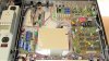
Today I have the cover removed from the Counter module to get a better idea of what's involved. The mounting brackets on each side are underneath harnesses which present a challenge to removing the assembly. The Power Supply PCB wire bundle is the least problem. The bundle on the OTHER side next to the Control Logic PCB is much stiffer and totally in the way. I see another of those infamous RIBBON CABLES that delaminate if you "touch them inappropriately." :nono:

MR80_counter_I.jpg


Best bet for this workbench would be IMHO to leave the ribbon alone and tip the module forward for recapping. To make removal of the counter box easier I'd pull the Control Logic PCB <8> first.. and recap it as well.


Caps to replace

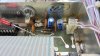
Here are views of the caps we're discussing... though I'm fully prepared for the caps NOT to be at fault.

MR80_counter_II.jpg

MR80_counter_III.jpg


Time to get a few more parts on order from Mouser.. probably Nichicon radial VR series.


-Greg
 
Last edited:
Back
Top Bottom