• The move to the new server is done. There are some software and database maintenance updates in process. This has us passing the hat around to help out. We appreciate any donations. Seriously, even a dollar helps. The payment page may be found here - https://www.audiokarma.org/support.html

My 6L6GC amp build thread

I don't mean to keep adding to this thread so often... Though I use it for my reference as well.

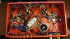
I have now removed the mess of 22AWG stranded ground wires, and started installing a solid 14AWG ground bus. Also relocated the rectifiers to the other side of the choke, so they are closer to the filter caps and farther from the preamp circuits. I can shield the RCA jacks easy enough if needed.

Made center taps for the 6SL7/6SN7 heaters using 220 ohm resistors, and it helped a lot. I'm going to change those to 100 ohm tomorrow.

Mounted the filter caps properly too. I hated to remove the OPT to make a couple holes under it, but it was worth the time. Now I just need a 500V 47uf or 100uf axial lead cap for the first filter before the choke.

IMG_0025.jpg
 
Last edited:
But OMG is this thing loud! I was worried about the balance control attenuating it too much, but I think it might be ok after all. With the balance control bypassed and the volume half way up, it's probably near full output.

If you need to squelch a little gain, you can always go back to the original cathode resistors from the original 6EU7 preamp circuit (instead of using the bypassed resistor). That might take a dB or so off the gain.

Regards,
Gordon.
 
If you need to squelch a little gain, you can always go back to the original cathode resistors from the original 6EU7 preamp circuit (instead of using the bypassed resistor). That might take a dB or so off the gain.

Regards,
Gordon.

Actually I might need to increase the gain even more, once the balance pot is connected. Since it is a standard pot, it will cut the volume by about half when centered. I'm hoping I'll be able to add some bypass resistors to make it a bit louder at center position though. I was never able to find a 1M dedicated balance pot.
 
Just a quick update, and a couple questions:

With the new ground bus, the hum is MUCH quieter. Though still annoying enough that I'm going to move to DC filaments if I have to. I also verified that the hum is coming from the preamp. When the balance control (which is between preamp and power amp) is turned to one side, the hum goes away in the other.

There is currently 25.5 volts on the 6L6GC cathodes. Should I leave it where it's at, or push it up a hair closer to the max of 30? Reason being, is I'm only getting 240V on the 6SN7/6SL7 plates. I measured 141 ohms from the 6L6GC cathodes to ground, so where would my bias be at this point? If I recall, the plate voltage was about 450.

I could change the first dropping resistor, which would raise both the 6L6GC G2 and the 6SN7/6SL7 plates, or just change the second one and leave the G2 alone.


The other question I have is regarding the balance control. It attenuates the volume and high frequency response of both channels when centered, like I expected it to.

I can fix this with a pair of bypass caps, but I'm concerned that it will ground out the preamp on the opposite channel from what the balance is turned to. The preamp circuit says it needs a 100K load minimum, so should I just use 100K bypass resistors? It would probably at least give me some more volume at center position.

And maybe the HF response and volume will improve a bit when the preamp plate voltage is up where it needs to be, around 300v or so.


EDIT: regarding the bias... According to the Weber calculator I found, it's right at 50ma per tube.
Actual measured voltages (while not using the variac this time), which I used on the calculator:
Plates 445v
cathodes 26v
G2/screen 307v

6SN7/6SL7 plates 239v. Looks like I need a smaller dropping resistor than the stock HK250's 4.7k.
 
Last edited:
Max,

I think your cathode resistors are probably right. You could change them (as in the PM I sent you), but I don't think you need to. 6L6GC plates are rated at 30w; currently, you're at around 22 watts.

I'd think a good plan would be to raise the voltage at the screen supply (which would also raise the voltage on the following supply to the 6SN7/6SL7 stages) to where you wind up with right at 30v on the output tube cathodes with the current output stage cathode resistors (the setup that gives 141 ohms). That'd be around 24.5 watts dissipation per tube at idle (around 54ma per tube); 80% of rated dissipation at idle is a good point on a cathode-bias amp... this would be right about dead on. Also, you'd be right at some of the "textbook" alignments... around 110ma per pair idle. I'd think that should sound quite good.

One question- as for the "6SN7/6SL7 plates 239v"... is that from the supply cap, or actually on one of the plate pins of one of the tubes? If it's from the plate pin, that's a pretty good value. If it's from the supply, you probably want to go up to around 300v, at least...

Regards,
Gordon.
 
Max,

I think your cathode resistors are probably right. You could change them (as in the PM I sent you), but I don't think you need to. 6L6GC plates are rated at 30w; currently, you're at around 22 watts.

I'd think a good plan would be to raise the voltage at the screen supply (which would also raise the voltage on the following supply to the 6SN7/6SL7 stages) to where you wind up with right at 30v on the output tube cathodes with the current output stage cathode resistors (the setup that gives 141 ohms). That'd be around 24.5 watts dissipation per tube at idle (around 54ma per tube); 80% of rated dissipation at idle is a good point on a cathode-bias amp... this would be right about dead on. Also, you'd be right at some of the "textbook" alignments... around 110ma per pair idle. I'd think that should sound quite good.

One question- as for the "6SN7/6SL7 plates 239v"... is that from the supply cap, or actually on one of the plate pins of one of the tubes? If it's from the plate pin, that's a pretty good value. If it's from the supply, you probably want to go up to around 300v, at least...

Regards,
Gordon.

The 6SN7/6SL7 plate voltage was measured at the supply. I'm thinking I'll need about a 1K resistor in place of the 4.7K, and a 5.6 or 6K resistor where the 6.8K is. I have the 6 and 5.6K on hand to try, but I may have to make yet another parts order to get the 1K 3-5W resistor. I'll experiment with it and see what I get.

I don't really want to mess with the cathode circuit if I don't have to, since it's at the bottom layer of components. Interesting how that circuit is set up, with several smaller resistors shared instead of a single large resistor. Saves cost and space I suppose.
 
I think your cathode circuit is OK. You should be able to tune the idle current with the screen voltage. I wound up doing that with my Maggie 6L6 homebrew... and it worked just fine.

And the reason for the "distributed" resistors? Keeps all the resistors at or below power dissipation limits for 10 watt resistors, and allows for the balance pot to work (allows differential voltage to the grids)...

As for the resistor value required- have you got another 4.7K you could try temporarily paralleling with the existing 4.7K to see where it gets you, in the vicinity of the ballpark (2.35K)? That would at least let you know if your planned values make sense.

Regards,
Gordon.
 
Did some testing tonight with smaller resistors.

With a 5.6k for the first dropping resistor, and a 1k for the preamp dropping resistor, I got 294v at the preamp supply. The screen and cathode voltage didn't move much, because the preamp is pulling more current (sounds better too!). I'm going to put a 4.7k or 3.9k in tomorrow, and hopefully everything will be right where I want it.

One nice thing I noticed when testing, is that there is no sag on the supply for the 6L6GC plates at all. I cranked it to clipping, and it still sat right at 445v. Guess I don't need to worry about overloading it :D

According to the Weber calculator, the plate dissipation in the 6L6GC's is 19W each, with 45ma plate current, so I still have some room to raise the voltages a bit more.

If I could get rid of the stupid hum, this thing would sound incredible.


EDIT: Since I wasn't quite ready for bed yet, I gave the 3.9k a try. I got 440v plates, 337v screen, and 318v to the preamp. 28.7 volts on the cathodes. I think I'll call that good enough for now, and leave the power supply alone. The calculator shows 16 watts, 49ma on the plates.
 
Last edited:
hummm

If the new ground scheme cut down the hum then maybe that as far as grounding goes your good, and that you now have to focus on the input routing, residual psu hum getting through the filtering, or something I'm not thinking of??
 
If the new ground scheme cut down the hum then maybe that as far as grounding goes your good, and that you now have to focus on the input routing, residual psu hum getting through the filtering, or something I'm not thinking of??

I think at this point, the hum is either from the heaters of the 6SL7's, or radiated from the filament transformer that is mounted nearby which runs them. I can't move anything else around, but I may be able to install some shields.

I still get a very loud buzz if I disconnect the signal ground from the chassis. I wish I knew why. It's something to do with just the preamp circuit, because the power amp alone works fine with the isolated signal ground.
 
you might try and isolate the input jacks from the chassis and run their ground wires to the grounds of the local node of the gain stage that they feed.
Maybe cut some soup cans up and plop them over the power tranny's and choke to see if that helps a bit I did this in my preamp that has a dc heater supply and it helped out a lot, although the soup can looks kinda funny I'll eventually find something copper to replace the soup can.
The copper tape u mentioned earlier might help I have been wanting to get my hands on some of this stuff.
 
you might try and isolate the input jacks from the chassis and run their ground wires to the grounds of the local node of the gain stage that they feed.
Maybe cut some soup cans up and plop them over the power tranny's and choke to see if that helps a bit I did this in my preamp that has a dc heater supply and it helped out a lot, although the soup can looks kinda funny I'll eventually find something copper to replace the soup can.
The copper tape u mentioned earlier might help I have been wanting to get my hands on some of this stuff.

The jacks are isolated. In fact I'm not using them at the moment, just running the signal straight to the volume control.
 
Things are looking good so far. I've been listening to it for about 2 hours.

Looks like the bit of remaining hum is radiated from the transformers. When I put my hand around the PT, the hum gets quieter. Once I get the cover done, it should sound great.

One thing that surprised me is that it is only about 25 watts RMS, like the original HK-250. I wonder why all the extra voltage from the power supply didn't change the output power. I'm sure it has a lot more headroom than a stock HK250 though.

I need to see about changing the caps in the treble control to something a bit smaller. The midrange is pretty loud, and increases too much with the treble control.

The 6L6GC's have a cool purple glow inside them near the edges. I wish I could get a clear picture.
 
Any updates to this, in particular how does it look and sound with all the shielding in place?
 
I've been using it quite regularly with no issues. Still have not finished the covers for the transformers or the bottom of the chassis yet, though I hope to by the end of this Summer.
 
Thought you guys might like to see the underside of this beast as it currently sits. I'm debating whether or not to redo the preamp section.

It's been very reliable for the few hundred hours I've put on it so far. No failures at all, even with the chassis not being properly ventilated yet.

attachment.php
 

Attachments

  • amp-under.jpg
    amp-under.jpg
    82.6 KB · Views: 221
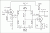
I've decided that I want to try another preamp circuit in this amp. Has anyone used this?

Hopefully I can use 6SL7GT's instead of 12AX7's.

attachment.php
 

Attachments

  • Amp-Tone-5-A-B-best.gif
    Amp-Tone-5-A-B-best.gif
    13.9 KB · Views: 267
Maxxarcade,
I've read this post today and am wondering if the hum problem has been resolved. During my review of the pictures and the text, a nagging thought has come to me pertaining to chassis grounding of the solid wire ground bus wires. There does not appear to be a solid connection between the bus and the chassis which means that the solid wire ground bus may be floating, i.e. isolated from the chassis. This could be the problem which is causing the hum you are experiencing. The inside of the chassis has been beautifully painted "Chevy Orange" which puts an insulating coat on top of the aluminum (or steel) chassis and may be the reason for such "float". To determine this, scratch a small area (1/4" X 1/4" or so) of the paint down to bare metal on the inside of the chassis, verify the power cord is disconnected and then with your DMM or VOM check resistance between the chassis and the wire ground bus. A high Ohm reading would indicate a "floating" ground bus whereas a near zero reading would indicate that the ground bus is suitably grounded to the chassis. In the event you determine the grounding bus is "floating", connect a wire between the bus and the scratched bare metal chassis point and power up the amp to see if the hum has gone away.
Bill
 
Back
Top Bottom