klamsoss
Be willing to fail and try again.
I picked up this Model 400 locally last summer with the intention of restoring it for use in our living room. I love my other Fisher gear, and my fiancee likes the glow from these big Fisher receivers. I won't say no if she endorses any audio purchase! Other projects have kept me busy, but I have been feeling increasingly guilty that I haven't done anything with this jewel.
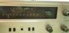
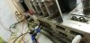
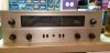
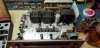
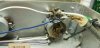
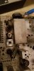
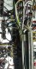
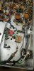
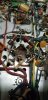
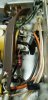
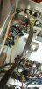
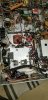
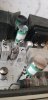
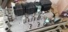
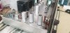
The chassis is in really good shape and will clean up well once I establish the electronics in safe working condition. It isn't rusty, doesn't stink or have sticky stuff all over it and most of the lettering is in great shape. I've posted a few "before" pictures to show the condition.
Electrically:
It has a good tube compliment (mostly original and a few American replacement tubes), OPTs test good (I get 264 and 273 ohms between pins 9 on each pair of output tube sockets, and then between the two red leads coming out of the OPTs and pins 9 on V14 though V17 I measure 127, 137, 133, and 140 ohms respectively. I believe these two sets of measurements are how one checks that OPTs are in good shape).
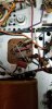
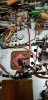
The small value high voltage caps in the power supply were physically broken, the power switch/volume pot is burned, but the volume works (photos of these are in the next post). I don't know how to test the main power transformer but for some reason thought that if I don't get open or continuity across the AC plug itself, that's an indication that the main transformer is probably not dead. I can't find where I read that though, so I can't rely on it. I hear the power transformers on these rarely blow, though, but the busted 0.01 caps and bad power switch worry me. The power switch is a common issue on these, though, I understand
My intention is to get it running properly first, then decide how far I want to take the modifications. I have some experience with very similar circuits in my FM-100-B and X-100-B which I have modified to some extent. Some, but not all, of the modifications and reliability improvements for those two units will transfer neatly.
I knew about the power switch when I got it, and considered just adding an inline switch and mounting it hidden on the side of the chassis, just behind the face plate. I may still do that but I like the properly working switch on my X-100-B, so I've inquired with Mark Oppat about a replacement for this model 400 and will use that if I can get one for a reasonable price.
I've ordered the hayseed hamfest can cap kit to cover the large value caps up top, and the "soda can" dual section 1000uF cap underneath. I did NOT get the "can" for underneath because I may end up wanting that real estate for EFB(tm), but that question is for a later post. I have stuffed cans in the past and it's not that hard, but it's messy and time consuming. The extra cost of the hayseed kit is worth the saved time and mess to me, at the moment. The kit should be here this coming week.
Other parts on order include the large wattage resistors that @larryderouin often recommends replacing with uprated pieces, and a few other parts I think I'll be needing. Most of the rest should be covered by parts I have on hand at my repair bench, though there are a few exceptions/questions, which I'll discuss in my next post.
I've also downloaded the "late model" (SN >48001) service manual since my SN is 72499 AM. For the record, I have the -AX OPTs and 6 IF/RF limiter tubes. I believe this is the correct manual for me, but I know there are at least a few examples of model 400s out there which appear not to exactly match any of the available service manuals. I have reviewed the thread on the various OPT and manual issues, but I can't follow them in their entirety. Hopefully folks will weigh in as the differences become relevant.
I'm modeling much of my work off of several of the very helpful threads by resident expert @dcgillespie Dave Gillespie. This includes the "Reference 400" thread (https://audiokarma.org/forums/index.php?threads/a-reference-400-restoration-modification.870612/ ), the thread on Fisher FM improvements ( https://audiokarma.org/forums/index...er-fm-stereo-mpx-tuners-and-receivers.708033/ ), the thread on improving the 400 (https://audiokarma.org/forums/index.php?threads/improving-the-fisher-400.511867/ ), and a few others. I'm incredibly grateful for the wisdom shared by all in these threads, especially Dave and Larry. I am aware of the threads. I have studied them. I will return to them as I make progress. However, I don't yet have the knowledge to fully understand them and confidently implement each of the updates/improvements described therein. I'll return to/reference them as my work progresses so that my thread can hopefully serve as a bit of a guide for others who, like me, aren't quite beginners but are only maybe sophomores (an occasionally sophomoric ) in terms of knowledge about these units, and want to learn more.
Okay... on to the work!!
Even though I haven't yet tested the main power transformer in a way that I feel I can rely on, I've gone ahead and started with a few things that I believe are consistent regardless of what "version" 400 I have:
Triple cleaning all the contacts, pots and switches with appropriate deoxit formulas: D5 for switches and contacts, F5 for the treble, bass, and balance pots.
I've replaced the physically broken 0.1 uF power supply bypass caps (C63 and C64 in my service manual) with appropriately rated film pieces.
I've installed a CL-90 ICL on the incoming AC leg which goes to the rectifier, NOT the leg that goes to the fuse (which is how I did it in my X-100-B). I think it doesn't really matter which leg of the power cord it goes on. It just needs to be in there.
The 100uF 25V electrolytic which is crammed over in that corner (C42 in my service manual) has also been replaced with a new Nichicon 50V rated piece. It is interesting here that the positive side of this capacitor goes to ground, rather than the negative. That's something that I double and triple checked.
The 1uF electrolytic capacitor in the tuner section (C210 in my service manual) has been replaced with an appropriately rated film which I have not yet tied in fully (more on that in my next post).
My plan is to replace all of the electrolytics and other the main power supply components (diodes, rectifier) before powering up to establish general functionality. From there, I'll perform updates and modifications.
This seems like enough for one post, but I'll be coming back. In my next post (later today) I'll describe some of the issues I want to understand better, questions I have related to appropriate parts, and outline some of the goals I have already developed for this resto-mod. Meantime, if anyone can advise on how to verify that my main power transformer is good, I'd appreciate it!
The chassis is in really good shape and will clean up well once I establish the electronics in safe working condition. It isn't rusty, doesn't stink or have sticky stuff all over it and most of the lettering is in great shape. I've posted a few "before" pictures to show the condition.
Electrically:
It has a good tube compliment (mostly original and a few American replacement tubes), OPTs test good (I get 264 and 273 ohms between pins 9 on each pair of output tube sockets, and then between the two red leads coming out of the OPTs and pins 9 on V14 though V17 I measure 127, 137, 133, and 140 ohms respectively. I believe these two sets of measurements are how one checks that OPTs are in good shape).
The small value high voltage caps in the power supply were physically broken, the power switch/volume pot is burned, but the volume works (photos of these are in the next post). I don't know how to test the main power transformer but for some reason thought that if I don't get open or continuity across the AC plug itself, that's an indication that the main transformer is probably not dead. I can't find where I read that though, so I can't rely on it. I hear the power transformers on these rarely blow, though, but the busted 0.01 caps and bad power switch worry me. The power switch is a common issue on these, though, I understand
My intention is to get it running properly first, then decide how far I want to take the modifications. I have some experience with very similar circuits in my FM-100-B and X-100-B which I have modified to some extent. Some, but not all, of the modifications and reliability improvements for those two units will transfer neatly.
I knew about the power switch when I got it, and considered just adding an inline switch and mounting it hidden on the side of the chassis, just behind the face plate. I may still do that but I like the properly working switch on my X-100-B, so I've inquired with Mark Oppat about a replacement for this model 400 and will use that if I can get one for a reasonable price.
I've ordered the hayseed hamfest can cap kit to cover the large value caps up top, and the "soda can" dual section 1000uF cap underneath. I did NOT get the "can" for underneath because I may end up wanting that real estate for EFB(tm), but that question is for a later post. I have stuffed cans in the past and it's not that hard, but it's messy and time consuming. The extra cost of the hayseed kit is worth the saved time and mess to me, at the moment. The kit should be here this coming week.
Other parts on order include the large wattage resistors that @larryderouin often recommends replacing with uprated pieces, and a few other parts I think I'll be needing. Most of the rest should be covered by parts I have on hand at my repair bench, though there are a few exceptions/questions, which I'll discuss in my next post.
I've also downloaded the "late model" (SN >48001) service manual since my SN is 72499 AM. For the record, I have the -AX OPTs and 6 IF/RF limiter tubes. I believe this is the correct manual for me, but I know there are at least a few examples of model 400s out there which appear not to exactly match any of the available service manuals. I have reviewed the thread on the various OPT and manual issues, but I can't follow them in their entirety. Hopefully folks will weigh in as the differences become relevant.
I'm modeling much of my work off of several of the very helpful threads by resident expert @dcgillespie Dave Gillespie. This includes the "Reference 400" thread (https://audiokarma.org/forums/index.php?threads/a-reference-400-restoration-modification.870612/ ), the thread on Fisher FM improvements ( https://audiokarma.org/forums/index...er-fm-stereo-mpx-tuners-and-receivers.708033/ ), the thread on improving the 400 (https://audiokarma.org/forums/index.php?threads/improving-the-fisher-400.511867/ ), and a few others. I'm incredibly grateful for the wisdom shared by all in these threads, especially Dave and Larry. I am aware of the threads. I have studied them. I will return to them as I make progress. However, I don't yet have the knowledge to fully understand them and confidently implement each of the updates/improvements described therein. I'll return to/reference them as my work progresses so that my thread can hopefully serve as a bit of a guide for others who, like me, aren't quite beginners but are only maybe sophomores (an occasionally sophomoric
) in terms of knowledge about these units, and want to learn more.Okay... on to the work!!
Even though I haven't yet tested the main power transformer in a way that I feel I can rely on, I've gone ahead and started with a few things that I believe are consistent regardless of what "version" 400 I have:
Triple cleaning all the contacts, pots and switches with appropriate deoxit formulas: D5 for switches and contacts, F5 for the treble, bass, and balance pots.
I've replaced the physically broken 0.1 uF power supply bypass caps (C63 and C64 in my service manual) with appropriately rated film pieces.
I've installed a CL-90 ICL on the incoming AC leg which goes to the rectifier, NOT the leg that goes to the fuse (which is how I did it in my X-100-B). I think it doesn't really matter which leg of the power cord it goes on. It just needs to be in there.
The 100uF 25V electrolytic which is crammed over in that corner (C42 in my service manual) has also been replaced with a new Nichicon 50V rated piece. It is interesting here that the positive side of this capacitor goes to ground, rather than the negative. That's something that I double and triple checked.
The 1uF electrolytic capacitor in the tuner section (C210 in my service manual) has been replaced with an appropriately rated film which I have not yet tied in fully (more on that in my next post).
My plan is to replace all of the electrolytics and other the main power supply components (diodes, rectifier) before powering up to establish general functionality. From there, I'll perform updates and modifications.
This seems like enough for one post, but I'll be coming back. In my next post (later today) I'll describe some of the issues I want to understand better, questions I have related to appropriate parts, and outline some of the goals I have already developed for this resto-mod. Meantime, if anyone can advise on how to verify that my main power transformer is good, I'd appreciate it!
Attachments
Last edited:



 ), but let's do some baseline functionality testing first.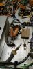


 I did not test the headphone output.
 Output is not even on both sides, but we're making progress...