• The move to the new server is done. There are some software and database maintenance updates in process. This has us passing the hat around to help out. We appreciate any donations. Seriously, even a dollar helps. The payment page may be found here - https://www.audiokarma.org/support.html

My Fisher 400 restoration and modification project

I got the distortion in check, somewhat, with the new tubes. Not sure where the remaining distortion is coming from, now, but there are a few possible sources. Will return to it soon. There was still a channel imbalance, which I traced to the volume knob. It’s seen better days, as the power switch on it is completely gone now, so I ordered a new one. It’s partly installed. There are 3 wires heading to the switch, but only two solder lugs on the switch. This is baffling to me, as is the fact that there is no metal cover on the switch. I assume the original metal cover was tossed by a prior owner when the switch burned up. Does anyone know how to tell which two should be connected to the same lug?
Unfortunately the threads on the pot are also not the same as the threads on the standoff nut that holds the pot in place, and to which the nut for the faceplate threads.

While I was waiting for the switch to come, I turned my attention to updating the bias network. The plan is EFB and IBAM on the same board, under the chassis, basically the way @Dave451 did in this thread:
https://audiokarma.org/forums/index.php?threads/newly-acquired-fisher-400.736364/page-2

Current sensing resistors went in with little drama other than that I discovered this unit has been tinkered with previously. As I desolderd the 1.2k high power resistor from the pin 1 lug on the tube 15 socket, I discovered that half the lug is completely gone. This and a handful of other little things show me that someone was in here at some point in the past and was a bit ham-fisted. I think I can work with what is left of it, but I won’t want to solder there more than one more time, so I think the appropriate thing to do is sort out my bias now, and catch up with the headphone and phono problems afterwards.

Still want to find out if it's okay to hook up my Tek 465b scope to this, since I have been told it is NOT okay to do so on the X-100-B. The 'scope is my preferred way of tracking down a signal problem. So once I know how the wires are supposed to connect up to the power switch and I can find a replacement cover for it, and I get the EFB/IBAM board in there, I should be ready to take care of the rest, and do so without running my power tubes ragged.
 
The original switch had a separate connection for the rear AC outlets on the rear of the unit. The new replacement switches do not. You just connect the two wires together on the same lug on the new switch, works fine.
 
So the lead that comes right off the wall cord should be solo, and the other two wires can both go to the remaining lug?

Any ideas on where to find a cover for the switch?

If I am installing EFB and IBAM, do I still need to do the screen stabilizers and swap the coupling caps and grid resistors? A few threads imply that I do not, but I can't find anything that specifically says that's the case.
 
So the lead that comes right off the wall cord should be solo, and the other two wires can both go to the remaining lug?

Any ideas on where to find a cover for the switch?

If I am installing EFB and IBAM, do I still need to do the screen stabilizers and swap the coupling caps and grid resistors? A few threads imply that I do not, but I can't find anything that specifically says that's the case.
That should be correct, you can connect a meter to it to verify it is working as it should. I have a few units that are missing the cover, I didn't worry about it since they are very hard to find. Maybe a dab of silicone can be used if need be, I just left it alone. Screen resistors are needed, but with bias adjustment added the grid resistor change is not really needed.
 
As long as you keep bias in 75% to 80% range dissipation, you'll be OK. Screen resistors good cheap insurance in any event.
 
Screen stabs it is, unless there is a consensus that they would degrade sound quality, but I haven't seen that anywhere. Might be able to get some time in the next couple days for more work on this. We'll see.

Thanks for the help!
 
Ahh yes! This is an article that I should probably be revisiting on a regular basis until I reach a greater level of understanding about tube amplifiers in general. I read it several times when I was working on my X-100-B but clearly it's time to review. It's chock full of wisdom that is accessible even to relative idiots like myself.
 
Relative idiots make family gatherings that much more fun....:rflmao::rflmao:. As new stock tubes aren't as robust, and have dimensional tolerances that would make engineers from the 50's and 60's "CRINGE", Screen stab resistors are good "CHEAP" insurance. They are only pennies apiece, and minimize the chances of arcing in a new tube, and practically negate any arcing in domestic/euro tubes. Something that takes some time to just get it in your list of things to do automatically.
 
Having established some baseline of operation, over the past few weeks I have crossed off the following items on the to-do list:
  • installed a new power switch/volume control (I'll return to this in a later post)
  • replaced the 0.02 uF ceramic capacitors on the loudness contour switch with poly films
  • replaced the remaining coupling capacitors (the 630V ones) with CDE types
  • replaced most of the 'dog turd' capacitors in the FM section
  • new rubber grommets under the phono stage tube sockets
  • installed screen stability resistors
  • replaced the 7W 1200ohm dropping resistor on the screens with a 10W piece from ohmite
  • begun work on my EFB/IBAM board - this is the focus of this post.
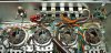
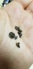
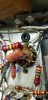
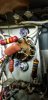
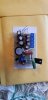
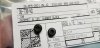
The pictures attached show the screen stability resistors installed (first shot), the process of replacing the rubber grommets for the phono tube sockets (the old ones almost completely disintegrated as I tried to remove them as seen in one of the photos), and my almost-done EFB/IBAM board. Sorry for them being out of order... the last two show the top side of the phono sockets with new grommets and the actual grommets I used (along with the part number info from digikey). For size reference on the EFB/IBAM board, it's sitting on a business card, so it's pretty darn tiny and will fit into the area where the dual section 1000uF cap used to sit, with plenty of room to spare. The only thing left to put on there is the 1w 270k resistor, which I don't have on hand. I have a random assortment of 2w resistors including 240k and 300k, but no 270k. And I have a bunch of 0.6w at 270k ohms but that's not gonna cut it.

Anyway, I have established baseline function and know there will be some effort necessary to resolve several issues (phono section, channel imbalance, headphone output). In order to save some abuse on the output tubes while I track down these issues, I am putting together my EFB/IBAM board and will install that next. Then I can take my time troubleshooting without worrying that I'm burning up tubes, transformers, or anything else other than Duke Energy's finest kWhs.

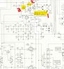
The attached schematic is pulled from the exceptionally helpful document attached to post 292 by @eduardsan1 in Dave's "Improving the Fisher 400" thread. The notes on my attachment will be helpful for following these questions. For these questions, the "first" KSA is the first one in the EFB circuit after the diode rectifier array.

1. It looks like the wiper on the EFB 10k bias pot connects to the same side of that pot as the 22k resistor and the base of the "first" KSA1013 and collector of the "second" KSA1013. Is that correct?

2. I see on Dave's original EFB for the Fisher 400 thread that on the emitter of the "first" KSA has a 4.7uF and 10k ohm resistor to ground before going to the grid resistors. In other threads, those two components seem to be eliminated when the EFB modification is used in conjunction with the IBAM modification. Is that correct or should those components be left in place?

3. Also in Dave's original EFB for 400 thread, the 47k ohm resistor coming off the other side of the bias pot is a 39k resistor. If I recall correctly, the change to a 47k resistor was out of convenience and seemed to allow a wider range of tubes to be used, but I can't specifically find that in the thread anywhere now that I am looking back at it.

4. Finally, is there a way to test the EFB/IBAM board out to make sure I have it all set up properly before I "go live" with it feeding the actual power amplifier?
 

Attachments

  • 20210430_233218.jpg
    20210430_233218.jpg
    111.1 KB · Views: 101
  • 20210429_233351.jpg
    20210429_233351.jpg
    90.6 KB · Views: 90
  • 20210429_233831.jpg
    20210429_233831.jpg
    50.3 KB · Views: 83
  • 20210429_234036.jpg
    20210429_234036.jpg
    76.7 KB · Views: 82
  • 20210429_234506.jpg
    20210429_234506.jpg
    51.4 KB · Views: 82
  • 20210429_235223.jpg
    20210429_235223.jpg
    75.8 KB · Views: 83
  • 20210504_154049.jpg
    20210504_154049.jpg
    55.9 KB · Views: 83
  • 20210429_235455.jpg
    20210429_235455.jpg
    131.5 KB · Views: 80
  • 20210429_233907.jpg
    20210429_233907.jpg
    75.9 KB · Views: 82
  • 400 efb ibam mod q.jpg
    400 efb ibam mod q.jpg
    138.5 KB · Views: 81
Last edited:
Just saw that for some reason the schematic I was trying to attach to my last post didn't work. I've added it now. Sorry about that!
 
After reviewing Dave's thread in detail for a while, I think I have answered my first (yes), second (take those two components out), and third (use 47k) questions. So that's progress! I'll be stopping by the small electronics shop in town today to pick up the 1w 270k resistor I need (along with a few other small things, including pots I will need for the PI revision, which I plan to install once I have everything else working as it should).

I also picked up on the 33uF caps in the IBAM portion of my board needing to be dropped down to 4.7uF because the supply is coming from the EFB setup rather than the original design. One more item that I won't have to troubleshoot later on. I hope to install the EFB/IBAM board this weekend and get on to correcting the operational shortcomings elsewhere. I'm still a rookie with most of this so it takes me a long time to work things out. I'll feel a lot better knowing that as I slowly plod through my other troubleshooting, the rest of my receiver isn't burning itself up.

I previously mentioned I had put in a new power switch, but that I would return to the topic. Well, here we are...
I couldn't get a response from Mr. Oppat and ended up ordering one from a guy called "hifiaudio-" on the fleabay. DON'T make the same mistake.
I messaged that the threading on the new part (advertised as "exact copy") is not the same as the threading on the original fisher part. I asked him how he would like to resolve the issue. He suggested I "try harder or get a professional's help."
I've been wrenching on things for 30 years, but I don't need that experience to understand thread patterns. Anyone ordering such a part will be familiar with how it feels trying to thread a standard nut onto a metric bolt, or vice versa, which is exactly the situation with this part. I pointed this out and the response was "What do you want me to do? Fix your hands?".... Rude, insulting, unprofessional, unnecessary.

I wasn't expecting to need to use my tap and die set to make an expensive "exact copy" part fit, but I was able to make it work. However, my 400, and the new control do not have the metal cap that covers the power switch solder lugs. I was thinking of either using a tube shield and soldering it in place to the shell of the 2nd pot, or possibly cutting apart the top of a can cap and soldering THAT in place to the shell of the 2nd pot. Any thoughts?

Is that cover absolutely necessary? (I do plan to put the op-amp buffer in that area once I get to that stage...)
 
Last edited:
I noticed that for your screen stability resistors, you jumpered them with wires between each point, rather than using a thick piece of wire for a Bus and connecting them that way, as I have seen in other threads. Your way looks easier to me. Any rationale for either method?
 
Back
Top Bottom