• Please note that Audiokarma will be offline briefly for updates early on Monday morning, September 28th.

My SA - 7100 Drops in and out of Protection

Filter Caps

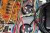
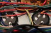
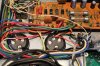
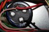
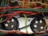
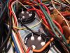
Pics as requested.
 

Attachments

  • IMG_2427.jpg
    IMG_2427.jpg
    69.5 KB · Views: 38
  • IMG_2428.jpg
    IMG_2428.jpg
    57 KB · Views: 33
  • IMG_2429.jpg
    IMG_2429.jpg
    87.3 KB · Views: 30
  • IMG_2430.jpg
    IMG_2430.jpg
    61.9 KB · Views: 31
  • IMG_2431.jpg
    IMG_2431.jpg
    61.8 KB · Views: 30
looks wired wrong to me ..
you tied negatives together
you need to replace both of them now
you should have ground to plus on one cap then to minus on the the other one .
then plus wires to the cap with plus terminal and negatives to other cap .
here is a simple diagram .....
PlusMinusPowerSupply.sch.01.jpeg
 
Last edited:
that pic only shows one cap ..
next time if you take your own pic before working on stuff you will have a good reference .
yes it cant work properly like that ..you are lucky they didn't explode ....kaboom ..
 
that pic only shows one cap ..
next time if you take your own pic before working on stuff you will have a good reference .
yes it cant work properly like that ..you are lucky they didn't explode ....kaboom ..

Funny you should say that. I took pics of everything but those filters..
Lucky I heard the fizzy noise and then I decided to switch it off ! Kaboom yes could have been..
Thank you very much for your help :thmbsp:
I'll place an order on Monday and revisit this when the new ones arrive.
Cheers mate
 
hope you put them in and are good to go, I will see if I have a pic showing both.

I usually draw a detailed diagram, I will also see if I have that.
 
Filter caps

looks wired wrong to me ..
you tied negatives together
you need to replace both of them now
you should have ground to plus on one cap then to minus on the the other one .
then plus wires to the cap with plus terminal and negatives to other cap .
here is a simple diagram .....
PlusMinusPowerSupply.sch.01.jpeg


Ok, to be clear, I just need to switch the wiring on the inner cap (Orange/Red) and ground.
The Orange/red wire to the minus and the ground to the plus.
The outer cap wiring remains the same.
 
hope you put them in and are good to go, I will see if I have a pic showing both.

I usually draw a detailed diagram, I will also see if I have that.

Hi Pat. If you mean the filter caps, no not yet. I don't have any spares.

Actually I still have the original ones, but I won't use these. defeats the purpose of the upgrade.
I'm going to have to place another order.

It would be great if you have a pic, I'd appreciate that mate, thanks.
 
Last edited:
ok on my pic you will see on that cap:

+ has 1 red wire/1 white wire
- has 1 black wire

other cap

the black from the - above goes to the + on the other cap along with another black wire
- has 1 green and one either red or orange (I am totally color blind) so I mark all my wires.

hope this helps.
 
ok just looked at your pics now, the cap you copied off mine is correct (red/white/black) the ones on the other cap are backwards.:yikes:
 
you can try the reversed cap, it's pretty much a short when backwards and if there was a DBT in circuit it didn't get exposed to much localized heat.
 
Hey there Mark and thanks for the info.
The cap with the wrong wiring has actually bulged slightly so I'm not confident in it's reliability.
I'll just change them both out and report back when done.
 
New Filter caps Installed

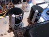
Hi Gents, I just got around to installing these new filter caps, wired/soldered correctly this time..:D
I'll bring up on DBT now and report back.
Then if all good, I'll ask for amp settings advice(wires still disconnected):thmbsp:
 

Attachments

  • DSC06032 - Copy.JPG
    DSC06032 - Copy.JPG
    215.6 KB · Views: 26
  • DSC06033 - Copy.JPG
    DSC06033 - Copy.JPG
    219.7 KB · Views: 25
  • DSC06034 - Copy.JPG
    DSC06034 - Copy.JPG
    204.6 KB · Views: 28
DBT test

Good Luck!

Ok. So i had a chance to hook it up to the DBT.

What happens is the bulb lights up very dimly for around a second and goes out completely.
The protection relay clicks and all appears normal. The power light remains on.
I left it on for around 20 secs and no smoke or anything strange going on.

I initially used a 60w, then a 100w bulb. I don't have any higher than these. Could it simply be that the bulb voltage is too low to register ?

Is it almost time for doing these :banana::banana::banana:
or are we still at :scratch2:
 
Amp Adjustments

Ok so I departed DBT and powered on.

All good from here. I left it on for approx 30 mins to settle then set Idle current (VR 3 and VR 4) to 29.9 mV. Spec calls for 30mV.

Then set Bias Offset ( VR 1 and VR 2) to 2 mV.
Spec calls for 10mV and sometimes I see guys adjust it to almost 0.00mV.

I'm guessing the 2mV is ok. Same as yours Pat ! :yes:

I'm going to re solder the wires and I should be good to go ?

I'm really feeling this coming on :yippy:
 
Mission Accomplished !

Yeah I was right ! :yippy::yippy::yippy: :banana: :banana: :banana: :D

Just finished putting it all back together, plugged it to my Sony TC 730 and putting it through its paces.

The sound is wonderful and strong. I'm very satisfied with the clarity and punchiness this amp delivers. Very clean sound with no static. Just perfect !

Bear in mind I'm using my monitor audio bookshelf speakers here in my mad scientists room. Although a full range speaker, They don't do it justice.

I'll have to hook up to my monster sets in my living room soon. Just can't right now.

I want to give out a huge thank you to everyone who helped me on this project.

Mark, Pat, Larry, and everybody else who chimed in to help. Thanks for your continued support and guidance. There were some stressful moments but we got through ok ! :thmbsp:

Note the pic below is the completed unit under sound test among good company..:D

Next on the to do list is the cosmetic treatment...
 
Last edited:
Back
Top Bottom